PERSONAL LIGHT INSPECTION
PROCEDURE
-
INSPECT MAP LIGHT ASSEMBLY
-
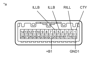
Text in Illustration *a Component without harness connected
(Map Light Assembly)
Inspect the interior light door switch.
-
Measure the resistance according to the value(s) in the table below.
Standard Resistance Tester Connection Condition Specified Condition 1 (CTY) - 2 (RILL) Interior light door switch OFF 10 kΩ or higher Interior light door switch ON 10 kΩ or higher Interior light door switch DOOR Below 1 Ω 15 (GND1) - 2 (RILL) Interior light door switch OFF 10 kΩ or higher Interior light door switch ON Below 1 Ω Interior light door switch DOOR 10 kΩ or higher If the result is not as specified, replace the map light assembly.
-
-
Inspect the map lights.
-
Connect a positive (+) lead from the auxiliary battery to terminal 21 (+B1) and a negative (-) lead to terminal 15 (GND1) or 1 (CTY).
Result Tester Connection Condition Specified Condition 21 (+B1) - 1 (CTY) Interior light door switch and map light switches OFF Map light LH and RH do not come on 21 (+B1) - 15 (GND1) Interior light door switch and map light switches OFF Map light LH and RH do not come on 21 (+B1) - 15 (GND1) Map light switch LH ON Map light LH comes on Map light switch RH ON Map light RH comes on Map light switch LH OFF
Map light switch RH OFF
Interior light door switch ON
Map light LH and RH come on 21 (+B1) - 1 (CTY) Map light switch LH OFF
Map light switch RH OFF
Interior light door switch DOOR
Map light LH and RH come on If the result is not as specified, replace the bulb or map light assembly.
-
-
Inspect the center console spot light.
-
Connect a positive (+) lead from the auxiliary battery to terminal 21 (+B1) and a negative (-) lead to terminal 5 (ILLB) or 6 (ILLB).
Result Tester Connection Condition Specified Condition 21 (+B1) - 5 (ILLB) Auxiliary battery positive (+) → Terminal 21 (+B1)
Auxiliary battery positive (-) → Terminal 5 (ILLB)
Center console spot light (red) comes on 21 (+B1) - 6 (ILLB) Auxiliary battery positive (+) → Terminal 21 (+B1)
Auxiliary battery positive (-) → Terminal 6 (ILLB)
Center console spot light (blue) comes on If the result is not as specified, replace the map light assembly.
-
-
Measure the resistance according to the value(s) in the table below.
Standard Resistance Tester Connection Condition Specified Condition 1 (CTY) - 2 (RILL) Interior light door switch DOOR Below 1 Ω If the result is not as specified, replace the map light assembly.
-