ENTRY AND START SYSTEM(for Start Function) Power Source Mode does not Change to ON (READY)
DESCRIPTION
When the electronic key is in the cabin and the power switch is pressed, the power management control ECU receives a signal and changes the power source mode. In addition, when the power switch is pressed with park (P) selected and the brake pedal depressed, the hybrid control system turns on (READY).
Tech Tips
-
When the power management control ECU is replaced with a new one and the cable is connected to the negative (-) auxiliary battery terminal, the power source mode changes to on (IG).
-
When the auxiliary battery cable is disconnected and reconnected, the power source returns to the mode it was in before the auxiliary battery cable was disconnected.
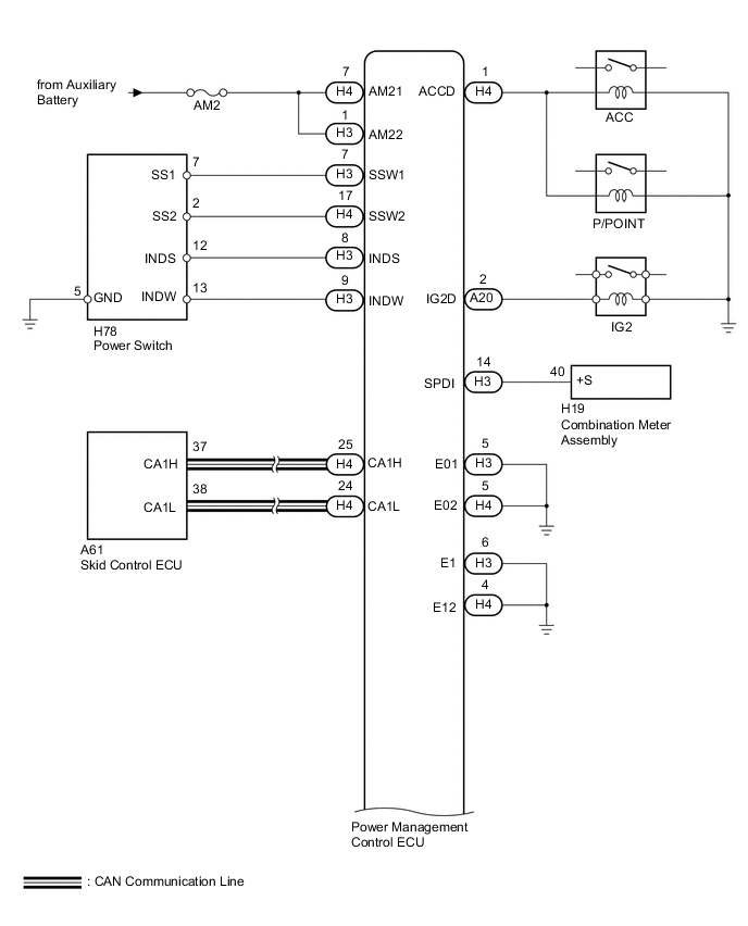
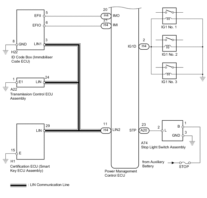
WIRING DIAGRAM
CAUTION / NOTICE / HINT
Note
-
Inspect the fuses for circuits related to this system before performing the following inspection procedure.
-
When using the intelligent tester with the power switch off, perform either of the following: 1) Turn a courtesy light switch on and off at intervals of 1.5 seconds or less until communication between the intelligent tester and vehicle begins, or 2) connect the intelligent tester to the vehicle, select the vehicle type under manual mode, and then enter the following menus:
for Power Source Control: Body / Power Source Control / DTC.
for Entry&Start: Body / Entry&Start / DTC.
-
The entry and start system uses multiplex communication. First perform the inspections in "How to Proceed with Troubleshooting" to confirm that there are no communication malfunctions before proceeding with troubleshooting Click here.
-
If the entry and start system is disabled through the customize function, enable the system before performing troubleshooting Click here.
-
Inspect the fuses of circuits related to this system before performing the following inspection procedure.
-
When replacing the certification ECU (smart key ECU assembly) or ID code box (immobiliser code ECU), registration must be performed refer to the Service Bulletin.
-
After completing repairs, confirm that the problem does not occur.
Tech Tips
| Problem Symptom | Data List Item | Active Test Item |
|---|---|---|
| Power Source Mode does not Change to ON (READY) |
Power Source Control
Entry&Start |
- |
PROCEDURE
-
CHECK HYBRID CONTROL SYSTEM READY ON
-
Place the electrical key on the driver seat.
-
Depress the brake pedal.
-
Check that the power switch indicator light is green. Then press the power switch to check if the hybrid control system turns on (READY).
OK Power source mode becomes on (READY).
OK 
END (HYBRID CONTROL SYSTEM PERMISSION CONDITIONS WERE NOT SATISFIED)
NG 
-
-
CHECK FOR DTC
-
Connect the intelligent tester to the DLC3.
-
Turn the power switch on (IG).
-
Turn the intelligent tester on.
-
Enter the following menus: Powertrain / Hybrid Control / DTC.
-
Check for DTCs.
OK DTC is not output.
NG
GO TO HYBRID CONTROL SYSTEM (DIAGNOSTIC TROUBLE CODE CHART) Click here
OK
-
-
CHECK FOR DTC
-
Entry the following menus: Body / Power Source Control / Data List.
-
Check for DTCs.
OK DTC is not output.
NG
GO TO DIAGNOSTIC TROUBLE CODE CHART Click here
OK
-
-
CHECK POWER SOURCE CONDITION
-
Check the power source mode change.
-
When the key is inside the vehicle and the park (P) is selected, check that pressing the power switch causes the power source mode to change.
Result Result Proceed to off → on (ACC) → on (IG) → off A Power source mode does not change to on (IG and ACC) B Power source mode does not change to on (IG) C Power source mode does not change to on (ACC) D
-
B
GO TO OTHER DIAGNOSIS PROCEDURE (Power Source Mode does not Change to ON (IG and ACC)) Click here
C
GO TO OTHER DIAGNOSIS PROCEDURE (Power Source Mode does not Change to ON (IG)) Click here
D
GO TO OTHER DIAGNOSIS PROCEDURE (Power Source Mode does not Change to ON (ACC)) Click here
A
-
-
READ VALUE USING INTELLIGENT TESTER (STOP LIGHT SWITCH ASSEMBLY)
-
Connect the intelligent tester to the DLC3.
-
Turn the power switch on (IG).
-
Turn the intelligent tester on.
-
Enter the following menus: Body / Power Source Control / Data List.
-
Read the Data List according to the display on the intelligent tester.
Power Source Control Tester Display Measurement Item/Range Normal Condition Diagnostic Note Stop Light Switch1 Stop light switch 1/ON or OFF ON: Brake pedal depressed
OFF: Brake pedal released
- OK ON (brake pedal is depressed) and OFF (brake pedal is released) appear on the screen.
NG 
CHECK HARNESS AND CONNECTOR (STOP LIGHT SWITCH ASSEMBLY - POWER SOURCE AND BODY GROUND) Click here
OK
-
-
READ VALUE USING INTELLIGENT TESTER (L CODE)
-
Connect the intelligent tester to the DLC3.
-
Turn the power switch on (IG).
-
Turn the intelligent tester on.
-
Enter the following menus: Body / Entry&Start / Data List.
-
Read the Data List according to the display on the intelligent tester.
Entry&Start Tester Display Measurement Item/Range Normal Condition Diagnostic Note L Code Check L code certification result/OK or NG OK: L code certification result normal
NG: L code certification result abnormal
- OK OK appears on the screen.
NG
REPLACE TRANSMISSION CONTROL ECU ASSEMBLY Click here
OK
-
-
READ VALUE USING INTELLIGENT TESTER (ENGINE START REQUEST)
-
Connect the intelligent tester to the DLC3.
-
Turn the power switch on (IG).
-
Turn the intelligent tester on.
-
Enter the following menus: Body / Entry&Start / Data List.
-
Read the Data List according to the display on the intelligent tester.
Entry&Start Tester Display Measurement Item/Range Normal Condition Diagnostic Note Engine Start Request Start request signal response/OK or NG OK: Start request condition signal received
NG: Start request condition signal not received
- OK OK appears on the screen. Result Result Proceed to OK A NG B
B
REPLACE TRANSMISSION CONTROL ECU ASSEMBLY Click here
A
-
-
READ VALUE USING INTELLIGENT TESTER (S CODE)
-
Connect the intelligent tester to the DLC3.
-
Turn the power switch on (IG).
-
Turn the intelligent tester on.
-
Enter the following menus: Body / Entry&Start / Data List.
-
Read the Data List according to the display on the intelligent tester.
Entry&Start Tester Display Measurement Item/Range Normal Condition Diagnostic Note S Code Check S code certification result/OK or NG OK: S code certification result normal
NG: S code certification result abnormal
- OK OK appears on the screen.
NG
REPLACE CERTIFICATION ECU (SMART KEY ECU ASSEMBLY) Click here
OK
-
-
CHECK ID CODE BOX (IMMOBILISER CODE ECU)
-
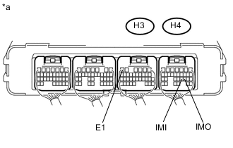
Text in Illustration *a Component with harness connected
(Power Management Control ECU)
Measure the voltage according to the value(s) in the table below.
-
Waveform 1
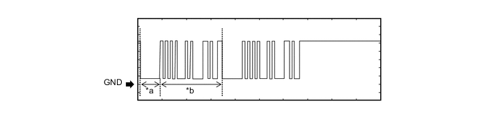
Text in Illustration *a Approximately 160 ms *b Approximately 510 ms Measurement Condition Item Content Tester Connection H4-20 (IMO) - H3-6 (E1) Tool Setting 2 V/DIV., 200 ms/DIV. Condition Within 3 seconds of hybrid control system start or within 3 seconds of power switch turned on (IG) after auxiliary battery cable disconnected and reconnected -
Waveform 2
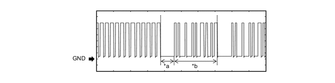
Text in Illustration *a Approximately 160 ms *b Approximately 510 ms Measurement Condition Item Content Tester Connection H4-21 (IMI) - H3-6 (E1) Tool Setting 2 V/DIV., 200 ms/DIV. Condition Power switch on (IG) OK The waveform is displayed as shown in illustration.
-
NG
REPLACE ID CODE BOX (IMMOBILISER CODE ECU)
OK
-
-
READ VALUE USING INTELLIGENT TESTER
-
Connect the intelligent tester to the DLC3.
-
Turn the power switch on (IG).
-
Turn the intelligent tester on.
-
Enter the following menus: Body / Power Source Control / Data List.
-
Read the Data List according to the display on the intelligent tester.
Power Source Control Tester Display Measurement Item/Range Normal Condition Diagnostic Note Starter Request Signal Hybrid control system start request signal / ON or OFF ON: STSW signal is on
OFF: STSW signal is off
- OK Data List display changes when the power switch is operated.
OK
GO TO HYBRID CONTROL SYSTEM Click here
NG
REPLACE POWER MANAGEMENT CONTROL ECU Click here
-
-
CHECK HARNESS AND CONNECTOR (STOP LIGHT SWITCH ASSEMBLY - POWER SOURCE AND BODY GROUND)
-
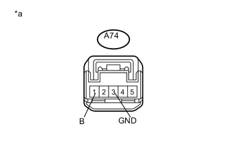
Text in Illustration *a Front view of wire harness connector
(to Stop Light Switch Assembly)
Disconnect the A74 stop light switch assembly connector.
-
Measure the voltage and resistance according to the value(s) in the table below.
Standard Voltage Tester Connection Condition Specified Condition A74-1 (B) - Body ground Power Switch off 11 to 14 V Standard Resistance Tester Connection Condition Specified Condition A74-3 (GND) - Body ground Always Below 1 Ω
NG
REPAIR OR REPLACE HARNESS OR CONNECTOR
OK
-
-
INSPECT STOP LIGHT SWITCH ASSEMBLY
-
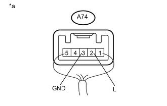
Text in Illustration *a Component with harness connected
(Stop Light Switch Assembly)
Reconnect the A74 stop light switch assembly connector.
-
Measure the voltage according to the value(s) in the table below.
Standard Voltage Tester Connection Condition Specified Condition A74-2 (L) - A74-3 (GND) Power Switch off, brake pedal not depressed Below 1 V A74-2 (L) - A74-3 (GND) Power Switch off, brake pedal depressed 11 to 14 V
NG
REPLACE STOP LIGHT SWITCH ASSEMBLY Click here
OK
-
-
CHECK HARNESS AND CONNECTOR (POWER MANAGEMENT CONTROL ECU - STOP LIGHT SWITCH ASSEMBLY)
-
Disconnect the A20 power management control ECU connector.
-
Disconnect the A74 stop light switch assembly connector.
-
Measure the resistance according to the value(s) in the table below.
Standard Resistance Tester Connection Condition Specified Condition A20-23 (STP) - A74-2 (L) Always Below 1 Ω A20-23 (STP) - Body ground Always 10 kΩ or higher
OK
REPLACE POWER MANAGEMENT CONTROL ECU Click here
NG
REPAIR OR REPLACE HARNESS OR CONNECTOR
-
-
REPLACE TRANSMISSION CONTROL ECU ASSEMBLY
-
Replace transmission control ECU assembly Click here.
NEXT
-
-
CHECK HYBRID CONTROL SYSTEM READY ON
-
Place the electrical key on the driver seat.
-
Depress the brake pedal.
-
Check that the power switch indicator light is green. Then press the power switch to check if the hybrid control system turns on (READY).
OK Power source mode becomes on (READY).
OK
END (TRANSMISSION CONTROL ECU WAS DEFECTIVE)
NG
REPLACE ID CODE BOX (IMMOBILISER CODE ECU)
-
-
REPLACE CERTIFICATION ECU (SMART KEY ECU ASSEMBLY)
-
Replace the certification ECU (smart key ECU assembly).
NEXT
-
-
CHECK HYBRID CONTROL SYSTEM READY ON
-
Place the electrical key on the driver seat.
-
Depress the brake pedal.
-
Check that the power switch indicator light is green. Then press the power switch to check if the hybrid control system turns on (READY).
OK Power source mode becomes on (READY).
OK
END (CERTIFICATION ECU (SMART KEY ECU ASSEMBLY) WAS DEFECTIVE)
NG
REPLACE ID CODE BOX (IMMOBILISER CODE ECU)
-