WIRELESS DOOR LOCK CONTROL SYSTEM, Diagnostic DTC:B1242
| DTC Code | DTC Name |
|---|---|
| B1242 | Wireless Door Lock Tuner Circuit Malfunction |
DESCRIPTION
The door control receiver is used to receive electrical waves relating to the entry functions of the entry and start system. The certification ECU (smart key ECU assembly) decodes the requested entry and start system system operation by identifying a key code based on the electric waves received via the door control receiver. The door control receiver receives a signal from the electrical key transmitter and sends signals to the main body ECU (multiplex network body ECU) through the certification ECU (smart key ECU assembly). The certification ECU (smart key ECU assembly) then sends a command, according to the requested operation, to each ECU (ex. if door lock operation is requested, the certification ECU (smart key ECU assembly) sends a door lock command to the main body ECU (multiplex network body ECU)).
| DTC No. | DTC Detection Condition | Trouble Area |
|---|---|---|
| B1242 |
|
|
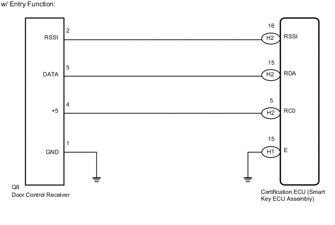
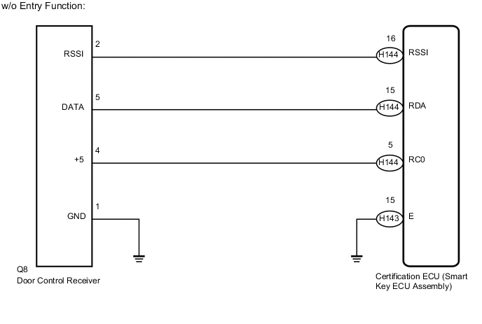
WIRING DIAGRAM
CAUTION / NOTICE / HINT
Note
-
When replacing or inspecting the door control receiver and wire harness, do not change the position or length of the wire harness. If the wire harness is too close to the door control receiver, entry and wireless function performance may be affected.
-
Before performing the inspection, check that there are no problems related to the CAN communication system.
PROCEDURE
-
CHECK HARNESS AND CONNECTOR (DOOR CONTROL RECEIVER - CERTIFICATION ECU AND BODY GROUND)
-
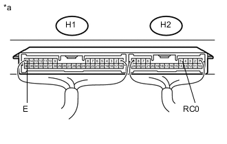
Disconnect the H1 and H2 certification ECU (smart key ECU assembly) connectors.*1
-
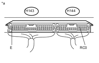
Disconnect the H143 and H144 certification ECU (smart key ECU assembly) connectors.*2
*1: w/ Entry Function
*2: w/o Entry Function
-
Disconnect the Q8 door control receiver connector.
-
Measure the resistance according to the value(s) in the table below.
Standard Resistance w/ Entry Function Tester Connection Condition Specified Condition H2-16 (RSSI) - Q8-2 (RSSI) Always Below 1 Ω H2-15 (RDA) - Q8-5 (DATA) Always Below 1 Ω H2-5 (RC0) - Q8-4 (+5) Always Below 1 Ω H1-15 (E) - Body ground Always Below 1 Ω Q8-1 (GND) - Body ground Always Below 1 Ω H2-16 (RSSI) or Q8-2 (RSSI) - Body ground Always 10 kΩ or higher H2-15 (RDA) or Q8-5 (DATA) - Body ground Always 10 kΩ or higher H2-5 (RC0) or Q8-4 (+5) - Body ground Always 10 kΩ or higher w/o Entry Function Tester Connection Condition Specified Condition H144-16 (RSSI) - Q8-2 (RSSI) Always Below 1 Ω H144-15 (RDA) - Q8-5 (DATA) Always Below 1 Ω H144-5 (RC0) - Q8-4 (+5) Always Below 1 Ω H143-15 (E) - Body ground Always Below 1 Ω Q8-1 (GND) - Body ground Always Below 1 Ω H144-16 (RSSI) or Q8-2 (RSSI) - Body ground Always 10 kΩ or higher H144-15 (RDA) or Q8-5 (DATA) - Body ground Always 10 kΩ or higher H144-5 (RC0) or Q8-4 (+5) - Body ground Always 10 kΩ or higher
NG 
REPAIR OR REPLACE HARNESS OR CONNECTOR
OK 
-
-
CHECK CERTIFICATION ECU (SMART KEY ECU ASSEMBLY)
-
Reconnect the H1 and H2 certification ECU (smart key ECU assembly) connectors.*1
-
Reconnect the H143 and H144 certification ECU (smart key ECU assembly) connectors.*2
*1: w/ Entry Function
*2: w/o Entry Function
-
Reconnect the Q8 door control receiver connector.
-
Measure the voltage according to the value(s) in the table below.
Standard Voltage w/ Entry Function Tester Connection Condition Specified Condition H2-5 (RC0) - H1-15 (E) Power switch off, all doors closed and electrical key transmitter switch pressed 4.5 to 5.5 V w/o Entry Function Tester Connection Condition Specified Condition H144-5 (RC0) - H143-15 (E) Power switch off, all doors closed and electrical key transmitter switch pressed 4.5 to 5.5 V Text in Illustration *a Component with harness connected
(Certification ECU (Smart Key ECU Assembly))
NG
REPLACE CERTIFICATION ECU (SMART KEY ECU ASSEMBLY)
OK
-
-
REPLACE DOOR CONTROL RECEIVER
-
Temporarily replace the door control receiver with a new one Click here.
NEXT
-
-
CHECK FOR DTC
-
Clear the DTCs Click here.
-
Recheck for DTCs.
OK DTC B1242 is not output.
OK
END (DOOR CONTROL RECEIVER WAS DEFECTIVE)
NG
REPLACE CERTIFICATION ECU (SMART KEY ECU ASSEMBLY)
-