CAN COMMUNICATION SYSTEM Check Bus 2 Lines for Short Circuit
DESCRIPTION
There may be a short circuit between the CAN main bus lines and/or CAN branch lines when the resistance between terminals 18 (CA4H) and 17 (CA4L) of the central gateway ECU (network gateway ECU) is below 54 Ω.
| Symptom | Trouble Area |
|---|---|
| Resistance between terminals 18 (CA4H) and 17 (CA4L) of the central gateway ECU (network gateway ECU) is below 54 Ω. |
|
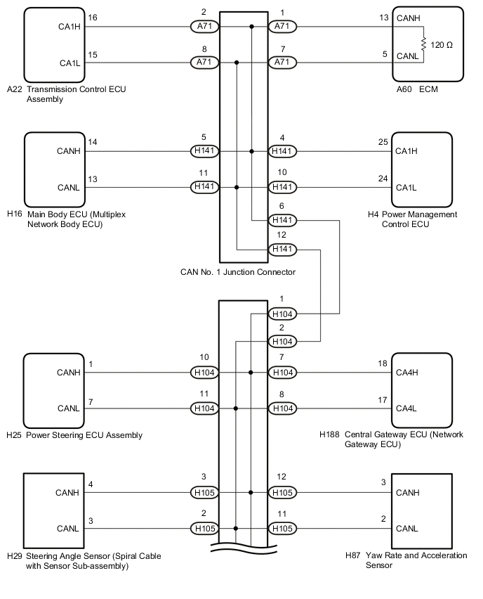
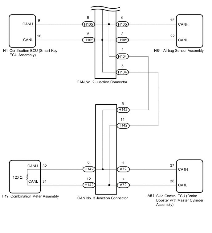
WIRING DIAGRAM
Figure 1. for LHD
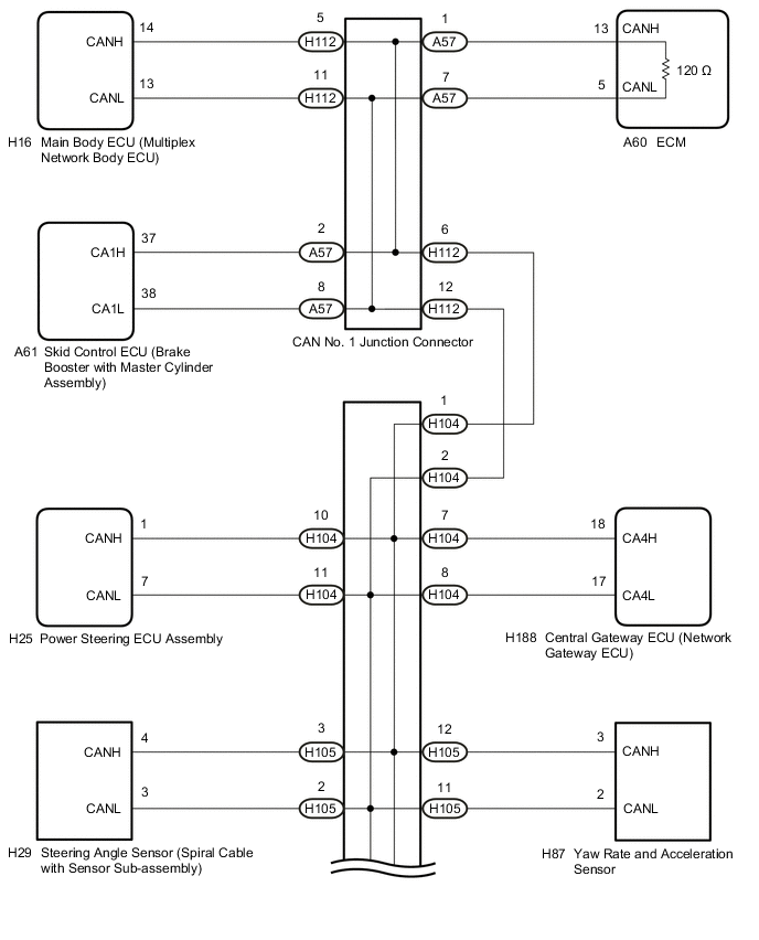
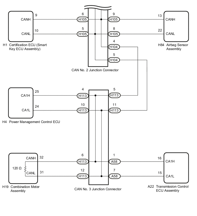
Figure 2. for RHD
CAUTION / NOTICE / HINT
Note
-
Because the order of diagnosis is important to allow correct diagnosis, make sure to begin troubleshooting using How to Proceed with Troubleshooting when CAN communication system related DTCs are output.
-
Before measuring the resistance of the CAN bus, turn the power switch off and leave the vehicle for 1 minute or more without operating the key or any switches, or opening or closing the doors. After that, disconnect the cable from the negative (-) auxiliary battery terminal and leave the vehicle for 1 minute or more before measuring the resistance.
-
After turning the power switch off, waiting time may be required before disconnecting the cable from the negative (-) auxiliary battery terminal. Therefore, make sure to read the disconnecting the cable from the negative (-) auxiliary battery terminal notices before proceeding with work.
-
After the repair, perform the CAN bus check and check that all the ECUs and sensors connected to the CAN communication system are displayed as normal.
Tech Tips
-
Before disconnecting related connectors for inspection, push in on each connector body to check that the connector is not loose or disconnected.
-
When a connector is disconnected, check that the terminals and connector body are not cracked, deformed or corroded.
PROCEDURE
-
CHECK VEHICLE TYPE
-
Check vehicle type.
Result Result Proceed to for LHD A for RHD B
B 
CHECK FOR SHORT IN CAN BUS LINES (COMBINATION METER ASSEMBLY) Click here
A 
-
-
CHECK FOR SHORT IN CAN BUS LINES (COMBINATION METER ASSEMBLY)
-
Disconnect the cable from the negative (-) auxiliary battery terminal.
-
Disconnect the H19 combination meter assembly connector.
-
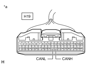
*a Front view of wire harness connector
(to Combination Meter Assembly)
Measure the resistance according to the value(s) in the table below.
Standard Resistance Tester Connection Condition Specified Condition H19-32 (CANH) - H19-31 (CANL) Cable disconnected from negative (-) auxiliary battery terminal 108 to 132 Ω Result Result OK NG
OK 
REPLACE COMBINATION METER ASSEMBLY Click here
NG
-
-
CHECK FOR SHORT IN CAN BUS LINES (ECM)
-
Reconnect the H19 combination meter assembly connector.
-
Disconnect the A60 ECM connector.
-
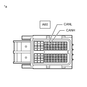
*a Front view of wire harness connector
(to ECM)
Measure the resistance according to the value(s) in the table below.
Standard Resistance Tester Connection Condition Specified Condition A60-13 (CANH) - A60-5 (CANL) Cable disconnected from negative (-) auxiliary battery terminal 108 to 132 Ω Result Result Proceed to OK (for 2ZR-FXE) A OK (for 5ZR-FXE) B NG C
A
REPLACE ECM Click here
B
REPLACE ECM Click here
C
-
-
CHECK FOR SHORT IN CAN BUS LINES (CAN NO. 2 JUNCTION CONNECTOR)
-
Reconnect the A60 ECM connector.
-
Disconnect the H104 CAN No. 2 junction connector.
-
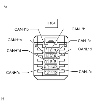
*a Front view of wire harness connector
(to CAN No. 2 Junction Connector)
*b to CAN No. 1 Junction Connector *c to CAN No. 3 Junction Connector *d to Central Gateway ECU (Network Gateway ECU) *e to Power Steering ECU Assembly Measure the resistance according to the value(s) in the table below.
Standard Resistance Tester Connection Condition Specified Condition Connected to H104-1 (CANH) - H104-2 (CANL) Cable disconnected from negative (-) auxiliary battery terminal 108 to 132 Ω CAN No. 1 junction connector H104-4 (CANH) - H104-5 (CANL) Cable disconnected from negative (-) auxiliary battery terminal 108 to 132 Ω CAN No. 3 junction connector H104-7 (CANH) - H104-8 (CANL) Cable disconnected from negative (-) auxiliary battery terminal 200 Ω or higher Central gateway ECU (network gateway ECU) H104-10 (CANH) - H104-11 (CANL) Cable disconnected from negative (-) auxiliary battery terminal 200 Ω or higher Power steering ECU assembly Result Result Proceed to OK A NG (Line to CAN No. 1 junction connector) B NG (Line to CAN No. 3 junction connector) C NG (Line to central gateway ECU (network gateway ECU)) D NG (Line to ECU or sensor) E
B
CHECK FOR SHORT IN CAN BUS LINES (CAN NO. 1 JUNCTION CONNECTOR) Click here
C
CHECK FOR SHORT IN CAN BUS LINES (CAN NO. 3 JUNCTION CONNECTOR) Click here
D
CHECK FOR SHORT IN CAN BUS LINES (CENTRAL GATEWAY ECU (NETWORK GATEWAY ECU)) Click here
E
CHECK FOR SHORT IN CAN BUS LINES (ECU OR SENSOR) Click here
A
-
-
CHECK FOR SHORT IN CAN BUS LINES (CAN NO. 2 JUNCTION CONNECTOR)
-
Disconnect the H105 CAN No. 2 junction connector.
-
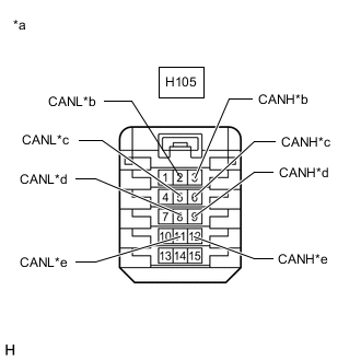
*a Front view of wire harness connector
(to CAN No. 2 Junction Connector)
*b to Steering Angle Sensor (Spiral Cable with Sensor Sub-assembly) *c to Certification ECU (Smart Key ECU Assembly) *d to Airbag Sensor Assembly *e to Yaw Rate and Acceleration Sensor Measure the resistance according to the value(s) in the table below.
Standard Resistance Tester Connection Condition Specified Condition Connected to H105-3 (CANH) - H105-2 (CANL) Cable disconnected from negative (-) auxiliary battery terminal 200 Ω or higher Steering angle sensor (spiral cable with sensor sub-assembly) H105-6 (CANH) - H105-5 (CANL) Cable disconnected from negative (-) auxiliary battery terminal 200 Ω or higher Certification ECU (smart key ECU assembly) H105-9 (CANH) - H105-8 (CANL) Cable disconnected from negative (-) auxiliary battery terminal 200 Ω or higher Airbag sensor assembly H105-12 (CANH) - H105-11 (CANL) Cable disconnected from negative (-) auxiliary battery terminal 200 Ω or higher Yaw rate and acceleration sensor Result Result Proceed to OK A NG (Line to ECU or sensor) B
A
REPLACE CAN NO. 2 JUNCTION CONNECTOR
B
GO TO STEP 11 Click here
-
-
CHECK FOR SHORT IN CAN BUS LINES (CAN NO. 1 JUNCTION CONNECTOR)
-
Reconnect the H104 CAN No. 2 junction connector.
-
Disconnect the H112 CAN No. 1 junction connector.
-
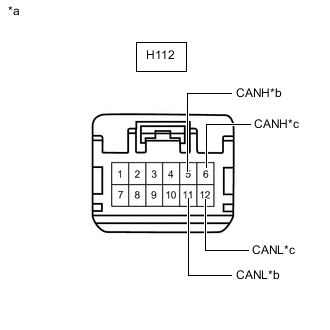
*a Front view of wire harness connector
(to CAN No. 1 Junction Connector)
*b to Main Body ECU (Multiplex Network Body ECU) *c to CAN No. 2 Junction Connector Measure the resistance according to the value(s) in the table below.
Standard Resistance Tester Connection Condition Specified Condition Connected to H112-5 (CANH) - H112-11 (CANL) Cable disconnected from negative (-) auxiliary battery terminal 200 Ω or higher Main body ECU (multiplex network body ECU) H112-6 (CANH) - H112-12 (CANL) Cable disconnected from negative (-) auxiliary battery terminal 200 Ω or higher CAN No. 2 junction connector Result Result Proceed to OK A NG (Line to CAN No. 2 junction connector) B NG (Line to ECU or sensor) C
B
REPAIR OR REPLACE CAN MAIN BUS LINES OR CONNECTOR (CAN NO. 1 JUNCTION CONNECTOR - CAN NO. 2 JUNCTION CONNECTOR)
C
GO TO STEP 11 Click here
A
-
-
CHECK FOR SHORT IN CAN BUS LINES (CAN NO. 1 JUNCTION CONNECTOR)
-
Disconnect the A57 CAN No. 1 junction connector.
-

*a Front view of wire harness connector
(to CAN No. 1 Junction Connector)
*b to ECM *c to Skid Control ECU (Brake Booster with Master Cylinder Assembly) Measure the resistance according to the value(s) in the table below.
Standard Resistance Tester Connection Condition Specified Condition Connected to A57-1 (CANH) - A57-7 (CANL) Cable disconnected from negative (-) auxiliary battery terminal 108 to 132 Ω ECM A57-2 (CANH) - A57-8 (CANL) Cable disconnected from negative (-) auxiliary battery terminal 200 Ω or higher Skid control ECU (brake booster with master cylinder assembly) Result Result Proceed to OK A NG (Line to ECM) B NG (Line to ECU or sensor) C
A
REPLACE CAN NO. 1 JUNCTION CONNECTOR
B
REPAIR OR REPLACE CAN MAIN BUS LINES OR CONNECTOR (ECM - CAN NO. 1 JUNCTION CONNECTOR)
C
GO TO STEP 11 Click here
-
-
CHECK FOR SHORT IN CAN BUS LINES (CAN NO. 3 JUNCTION CONNECTOR)
-
Reconnect the H104 CAN No. 2 junction connector.
-
Disconnect the H113 CAN No. 3 junction connector.
-
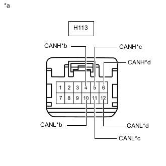
*a Front view of wire harness connector
(to CAN No. 3 Junction Connector)
*b to Power Management Control ECU *c to CAN No. 2 Junction Connector *d to Combination Meter Assembly Measure the resistance according to the value(s) in the table below.
Standard Resistance Tester Connection Condition Specified Condition Connected to H113-4 (CANH) - H113-10 (CANL) Cable disconnected from negative (-) auxiliary battery terminal 200 Ω or higher Power management control ECU H113-5 (CANH) - H113-11 (CANL) Cable disconnected from negative (-) auxiliary battery terminal 108 to 132 Ω CAN No. 2 junction connector H113-6 (CANH) - H113-12 (CANL) Cable disconnected from negative (-) auxiliary battery terminal 108 to 132 Ω Combination meter assembly Result Result Proceed to OK A NG (Line to CAN No. 2 junction connector) B NG (Line to Combination meter assembly) C
B
REPAIR OR REPLACE CAN MAIN BUS LINES OR CONNECTOR (CAN NO. 2 JUNCTION CONNECTOR - CAN NO. 3 JUNCTION CONNECTOR)
C
REPAIR OR REPLACE CAN MAIN BUS LINES OR CONNECTOR (COMBINATION METER ASSEMBLY - CAN NO. 3 JUNCTION CONNECTOR)
A
-
-
CHECK FOR SHORT IN CAN BUS LINES (CAN NO. 3 JUNCTION CONNECTOR)
-
Disconnect the A58 CAN No. 3 junction connector.
-

*a Front view of wire harness connector
(to CAN No. 3 Junction Connector)
*b to Transmission Control ECU Assembly Measure the resistance according to the value(s) in the table below.
Standard Resistance Tester Connection Condition Specified Condition Connected to A58-1 (CANH) - A58-7 (CANL) Cable disconnected from negative (-) auxiliary battery terminal 200 Ω or higher Transmission control ECU assembly Result Result Proceed to OK A NG (Line to ECU or sensor) B
A
REPLACE CAN NO. 3 JUNCTION CONNECTOR
B
GO TO STEP 11 Click here
-
-
CHECK FOR SHORT IN CAN BUS LINES (CENTRAL GATEWAY ECU (NETWORK GATEWAY ECU))
-
Reconnect the H104 CAN No. 2 junction connector.
-
Disconnect the H188 central gateway ECU (network gateway ECU) connector.
-
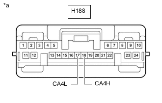
*a Front view of wire harness connector
(to Central Gateway ECU (Network Gateway ECU))
Measure the resistance according to the value(s) in the table below.
Standard Resistance Tester Connection Condition Specified Condition H188-18 (CA4H) - H188-17 (CA4L) Cable disconnected from negative (-) auxiliary battery terminal 54 to 69 Ω Result Result OK NG
OK
REPLACE CENTRAL GATEWAY ECU (NETWORK GATEWAY ECU) Click here
NG
REPAIR OR REPLACE CAN BRANCH LINES OR CONNECTOR (CAN NO. 2 JUNCTION CONNECTOR - CENTRAL GATEWAY ECU (NETWORK GATEWAY ECU))
-
-
CHECK FOR SHORT IN CAN BUS LINES (ECU OR SENSOR)
-
Reconnect all wire harness connectors.
-
Disconnect the connector that includes terminals CANH and CANL from the ECU or sensor to which the short circuited branch line is connected.
-
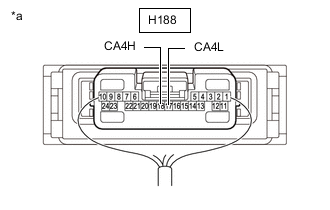
*a Component with harness connected
(Central Gateway ECU (Network Gateway ECU))
Measure the resistance according to the value(s) in the table below.
Standard Resistance Tester Connection Condition Specified Condition H188-18 (CA4H) - H188-17 (CA4L) Cable disconnected from negative (-) auxiliary battery terminal 54 to 69 Ω Tech Tips
-
If the resistance becomes normal (between 54 and 69 Ω) when the connector is disconnected from the ECU or sensor, there may be a short in the ECU or sensor.
-
If the resistance does not become normal when the connector is disconnected from the ECU or sensor, check for a short in the wire harness and repair or replace the wire harness or connector if necessary.
Result Result OK NG -
OK
REPLACE ECU OR SENSOR
NG
REPAIR OR REPLACE HARNESS OR CONNECTOR
-
-
CHECK FOR SHORT IN CAN BUS LINES (COMBINATION METER ASSEMBLY)
-
Disconnect the cable from the negative (-) auxiliary battery terminal.
-
Disconnect the H19 combination meter assembly connector.
-
*a Front view of wire harness connector
(to Combination Meter Assembly)
Measure the resistance according to the value(s) in the table below.
Standard Resistance Tester Connection Condition Specified Condition H19-32 (CANH) - H19-31 (CANL) Cable disconnected from negative (-) auxiliary battery terminal 108 to 132 Ω Result Result OK NG
OK
REPLACE COMBINATION METER ASSEMBLY Click here
NG
-
-
CHECK FOR SHORT IN CAN BUS LINES (ECM)
-
Reconnect the H19 combination meter assembly connector.
-
Disconnect the A60 ECM connector.
-
*a Front view of wire harness connector
(to ECM)
Measure the resistance according to the value(s) in the table below.
Standard Resistance Tester Connection Condition Specified Condition A60-13 (CANH) - A60-5 (CANL) Cable disconnected from negative (-) auxiliary battery terminal 108 to 132 Ω Result Result OK NG
OK
REPLACE ECM Click here
NG
-
-
CHECK FOR SHORT IN CAN BUS LINES (CAN NO. 2 JUNCTION CONNECTOR)
-
Reconnect the A60 ECM connector.
-
Disconnect the H104 CAN No. 2 junction connector.
-
*a Front view of wire harness connector
(to CAN No. 2 Junction Connector)
*b to CAN No. 1 Junction Connector *c to CAN No. 3 Junction Connector *d to Central Gateway ECU (Network Gateway ECU) *e to Power Steering ECU Assembly Measure the resistance according to the value(s) in the table below.
Standard Resistance Tester Connection Condition Specified Condition Connected to H104-1 (CANH) - H104-2 (CANL) Cable disconnected from negative (-) auxiliary battery terminal 108 to 132 Ω CAN No. 1 junction connector H104-4 (CANH) - H104-5 (CANL) Cable disconnected from negative (-) auxiliary battery terminal 108 to 132 Ω CAN No. 3 junction connector H104-7 (CANH) - H104-8 (CANL) Cable disconnected from negative (-) auxiliary battery terminal 200 Ω or higher Central gateway ECU (network gateway ECU) H104-10 (CANH) - H104-11 (CANL) Cable disconnected from negative (-) auxiliary battery terminal 200 Ω or higher Power steering ECU assembly Result Result Proceed to OK A NG (Line to CAN No. 1 junction connector) B NG (Line to CAN No. 3 junction connector) C NG (Line to central gateway ECU (network gateway ECU)) D NG (Line to ECU or sensor) E
B
CHECK FOR SHORT IN CAN BUS LINES (CAN NO. 1 JUNCTION CONNECTOR) Click here
C
CHECK FOR SHORT IN CAN BUS LINES (CAN NO. 3 JUNCTION CONNECTOR) Click here
D
CHECK FOR SHORT IN CAN BUS LINES (CENTRAL GATEWAY ECU (NETWORK GATEWAY ECU)) Click here
E
CHECK FOR SHORT IN CAN BUS LINES (ECU OR SENSOR) Click here
A
-
-
CHECK FOR SHORT IN CAN BUS LINES (CAN NO. 2 JUNCTION CONNECTOR)
-
Disconnect the H105 CAN No. 2 junction connector.
-
*a Front view of wire harness connector
(to CAN No. 2 Junction Connector)
*b to Steering Angle Sensor (Spiral Cable with Sensor Sub-assembly) *c to Certification ECU (Smart Key ECU Assembly) *d to Airbag Sensor Assembly *e to Yaw Rate and Acceleration Sensor Measure the resistance according to the value(s) in the table below.
Standard Resistance Tester Connection Condition Specified Condition Connected to H105-3 (CANH) - H105-2 (CANL) Cable disconnected from negative (-) auxiliary battery terminal 200 Ω or higher Steering angle sensor (spiral cable with sensor sub-assembly) H105-6 (CANH) - H105-5 (CANL) Cable disconnected from negative (-) auxiliary battery terminal 200 Ω or higher Certification ECU (smart key ECU assembly) H105-9 (CANH) - H105-8 (CANL) Cable disconnected from negative (-) auxiliary battery terminal 200 Ω or higher Airbag sensor assembly H105-12 (CANH) - H105-11 (CANL) Cable disconnected from negative (-) auxiliary battery terminal 200 Ω or higher Yaw rate and acceleration sensor Result Result Proceed to OK A NG (Line to ECU or sensor) B
A
REPLACE CAN NO. 2 JUNCTION CONNECTOR
B
GO TO STEP 21 Click here
-
-
CHECK FOR SHORT IN CAN BUS LINES (CAN NO. 1 JUNCTION CONNECTOR)
-
Reconnect the H104 CAN No. 2 junction connector.
-
Disconnect the H141 CAN No. 1 junction connector.
-
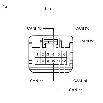
*a Front view of wire harness connector
(to CAN No. 1 Junction Connector)
*b to Power Management Control ECU *c to Main Body ECU (Multiplex Network Body ECU) *d to CAN No. 2 Junction Connector Measure the resistance according to the value(s) in the table below.
Standard Resistance Tester Connection Condition Specified Condition Connected to H141-4 (CANH) - H141-10 (CANL) Cable disconnected from negative (-) auxiliary battery terminal 200 Ω or higher Power management control ECU H141-5 (CANH) - H141-11 (CANL) Cable disconnected from negative (-) auxiliary battery terminal 200 Ω or higher Main body ECU (multiplex network body ECU) H141-6 (CANH) - H141-12 (CANL) Cable disconnected from negative (-) auxiliary battery terminal 108 to 132 Ω CAN No. 2 junction connector Result Result Proceed to OK A NG (Line to CAN No. 2 junction connector) B NG (Line to ECU or sensor) C
B
REPAIR OR REPLACE CAN MAIN BUS LINES OR CONNECTOR (CAN NO. 1 JUNCTION CONNECTOR - CAN NO. 2 JUNCTION CONNECTOR)
C
GO TO STEP 21 Click here
A
-
-
CHECK FOR SHORT IN CAN BUS LINES (CAN NO. 1 JUNCTION CONNECTOR)
-
Disconnect the A71 CAN No. 1 junction connector.
-
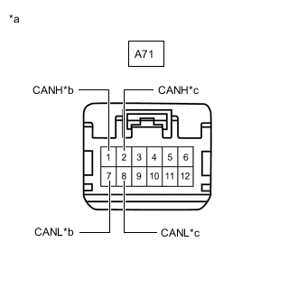
*a Front view of wire harness connector
(to CAN No. 1 Junction Connector)
*b to ECM *c to Transmission Control ECU Assembly Measure the resistance according to the value(s) in the table below.
Standard Resistance Tester Connection Condition Specified Condition Connected to A71-1 (CANH) - A71-7 (CANL) Cable disconnected from negative (-) auxiliary battery terminal 108 to 132 Ω ECM A71-2 (CANH) - A71-8 (CANL) Cable disconnected from negative (-) auxiliary battery terminal 200 Ω or higher Transmission control ECU assembly Result Result Proceed to OK A NG (Line to ECM) B NG (Line to ECU or sensor) C
A
REPLACE CAN NO. 1 JUNCTION CONNECTOR
B
REPAIR OR REPLACE CAN MAIN BUS LINES OR CONNECTOR (ECM - CAN NO. 1 JUNCTION CONNECTOR)
C
GO TO STEP 21 Click here
-
-
CHECK FOR SHORT IN CAN BUS LINES (CAN NO. 3 JUNCTION CONNECTOR)
-
Reconnect the H104 CAN No. 2 junction connector.
-
Disconnect the H142 CAN No. 3 junction connector.
-
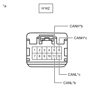
*a Front view of wire harness connector
(to CAN No. 3 Junction Connector)
*b to CAN No. 2 Junction Connector *c to Combination Meter Assembly Measure the resistance according to the value(s) in the table below.
Standard Resistance Tester Connection Condition Specified Condition Connected to H142-5 (CANH) - H142-11 (CANL) Cable disconnected from negative (-) auxiliary battery terminal 108 to 132 Ω CAN No. 2 junction connector H142-6 (CANH) - H142-12 (CANL) Cable disconnected from negative (-) auxiliary battery terminal 108 to 132 Ω Combination meter assembly Result Result Proceed to OK A NG (Line to CAN No. 2 junction connector) B NG (Line to Combination meter assembly) C
B
REPAIR OR REPLACE CAN MAIN BUS LINES OR CONNECTOR (CAN NO. 2 JUNCTION CONNECTOR - CAN NO. 3 JUNCTION CONNECTOR)
C
REPAIR OR REPLACE CAN MAIN BUS LINES OR CONNECTOR (COMBINATION METER ASSEMBLY - CAN NO. 3 JUNCTION CONNECTOR)
A
-
-
CHECK FOR SHORT IN CAN BUS LINES (CAN NO. 3 JUNCTION CONNECTOR)
-
Disconnect the A72 CAN No. 3 junction connector.
-
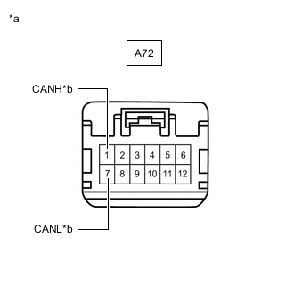
*a Front view of wire harness connector
(to CAN No. 3 Junction Connector)
*b to Skid Control ECU (Brake Booster with Master Cylinder Assembly) Measure the resistance according to the value(s) in the table below.
Standard Resistance Tester Connection Condition Specified Condition Connected to A72-1 (CANH) - A72-7 (CANL) Cable disconnected from negative (-) auxiliary battery terminal 200 Ω or higher Skid control ECU (brake booster with master cylinder assembly) Result Result Proceed to OK A NG (Line to ECU or sensor) B
A
REPLACE CAN NO. 3 JUNCTION CONNECTOR
B
GO TO STEP 21 Click here
-
-
CHECK FOR SHORT IN CAN BUS LINES (CENTRAL GATEWAY ECU (NETWORK GATEWAY ECU))
-
Reconnect the H104 CAN No. 2 junction connector.
-
Disconnect the H188 central gateway ECU (network gateway ECU) connector.
-
*a Front view of wire harness connector
(to Central Gateway ECU (Network Gateway ECU))
Measure the resistance according to the value(s) in the table below.
Standard Resistance Tester Connection Condition Specified Condition H188-18 (CA4H) - H188-17 (CA4L) Cable disconnected from negative (-) auxiliary battery terminal 54 to 69 Ω Result Result OK NG
OK
REPLACE CENTRAL GATEWAY ECU (NETWORK GATEWAY ECU) Click here
NG
REPAIR OR REPLACE CAN BRANCH LINES OR CONNECTOR (CAN NO. 2 JUNCTION CONNECTOR - CENTRAL GATEWAY ECU (NETWORK GATEWAY ECU))
-
-
CHECK FOR SHORT IN CAN BUS LINES (ECU OR SENSOR)
-
Reconnect all wire harness connectors.
-
Disconnect the connector that includes terminals CANH and CANL from the ECU or sensor to which the short circuited branch line is connected.
-
*a Component with harness connected
(Central Gateway ECU (Network Gateway ECU))
Measure the resistance according to the value(s) in the table below.
Standard Resistance Tester Connection Condition Specified Condition H188-18 (CA4H) - H188-17 (CA4L) Cable disconnected from negative (-) auxiliary battery terminal 54 to 69 Ω Tech Tips
-
If the resistance becomes normal (between 54 and 69 Ω) when the connector is disconnected from the ECU or sensor, there may be a short in the ECU or sensor.
-
If the resistance does not become normal when the connector is disconnected from the ECU or sensor, check for a short in the wire harness and repair or replace the wire harness or connector if necessary.
Result Result OK NG -
OK
REPLACE ECU OR SENSOR
NG
REPAIR OR REPLACE HARNESS OR CONNECTOR
-