CAN COMMUNICATION SYSTEM SYSTEM DIAGRAM
-
OVERALL CAN BUS DIAGRAM (for LHD)
-
The CAN communication system is composed of 6 buses.
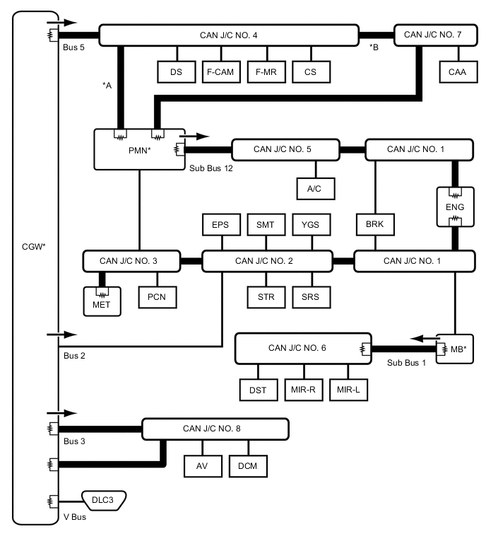
*A w/o Parking Assist Monitor System or w/ Parking Assist Monitor System (w/ Parallel Parking Assist Function) *B w/ Parking Assist Monitor System (w/o Parallel Parking Assist Function) 
CAN Main Bus Line 
Terminating Resistor 
CAN Branch Line * Gateway Function Equipped ECU 
Bus Monitoring Direction - - Connected to Code ECU/Sensor Name CAN DTC Storage Note - CGW Central Gateway ECU (Network Gateway ECU) - - V Bus DLC3 DLC3 - - Bus 2 MET Combination Meter Assembly Available - PMN Power Management Control ECU Available Gateway between the bus 2 and sub bus 12. PCN Transmission Control ECU Assembly Available - EPS Power Steering ECU Assembly Available - SMT Certification ECU (Smart Key ECU Assembly) Available - YGS Yaw Rate and Acceleration Sensor - - STR Steering Angle Sensor (Spiral Cable with Sensor Sub-assembly) - - SRS Airbag Sensor Assembly - - BRK Skid Control ECU (Brake Booster with Master Cylinder Assembly) Available - MB Main Body ECU (Multiplex Network Body ECU) Available
-
Gateway between the bus 2 and sub bus 1.
-
Connected to the LIN communication system.
ENG ECM Available - CAN J/C NO. 1 CAN No. 1 Junction Connector - - CAN J/C NO. 2 CAN No. 2 Junction Connector - - CAN J/C NO. 3 CAN No. 3 Junction Connector - - Bus 3 AV Radio Receiver Assembly Available
-
for Navigation Receiver Type
-
for Radio and Display Type
DCM DCM (Telematics Transceiver) Available
-
w/ Manual (SOS) Switch
-
The DCM (telematics transceiver) informs the radio receiver assembly of output DTCs through the USB communication line.
CAN J/C NO. 8 CAN No. 8 Junction Connector - - Bus 5 DS Driving Support ECU Assembly Available w/ Lexus Safety System + F-CAM Forward Recognition Camera Available w/ Lexus Safety System + F-MR Millimeter Wave Radar Sensor Assembly - w/ Lexus Safety System + CS Clearance Warning ECU Assembly Available w/ LEXUS Parking Assist-sensor System CAA Rear Television Camera Assembly Available w/ Parking Assist Monitor System (w/o Parallel Parking Assist Function) PMN Power Management Control ECU Available - CAN J/C NO. 4 CAN No. 4 Junction Connector - - CAN J/C NO. 7 CAN No. 7 Junction Connector - - Sub Bus 1 MB Main Body ECU (Multiplex Network Body ECU) Available
-
Gateway between the bus 2 and sub bus 1.
-
Connected to the LIN communication system.
MIR-L Outer Mirror Control ECU Assembly (Driver Side) Available w/ Seat Position Memory MIR-R Outer Mirror Control ECU Assembly (Front Passenger Side) Available w/ Seat Position Memory DST Position Control ECU and Switch Assembly - w/ Seat Position Memory CAN J/C NO. 6 CAN No. 6 Junction Connector - - Sub Bus 12 PMN Power Management Control ECU Available Gateway between the bus 2 and sub bus 12. A/C Air Conditioning Amplifier Assembly Available - BRK Skid Control ECU (Brake Booster with Master Cylinder Assembly) Available - ENG ECM Available - CAN J/C NO. 1 CAN No. 1 Junction Connector - - CAN J/C NO. 5 CAN No. 5 Junction Connector - - -
-
-
OVERALL CAN BUS DIAGRAM (for RHD)
-
The CAN communication system is composed of 6 buses.
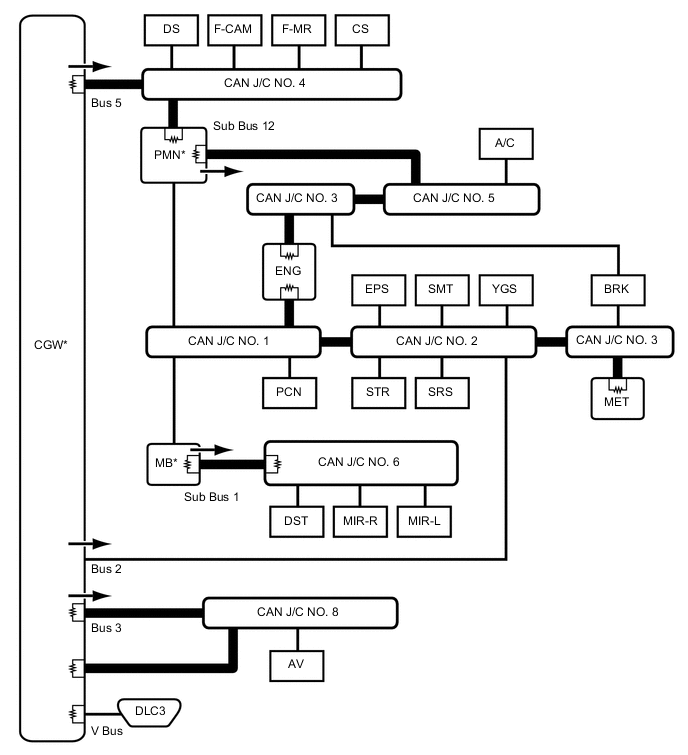
CAN Main Bus Line Terminating Resistor CAN Branch Line * Gateway Function Equipped ECU Bus Monitoring Direction - - Connected to Code ECU/Sensor Name CAN DTC Storage Note - CGW Central Gateway ECU (Network Gateway ECU) - - V Bus DLC3 DLC3 - - Bus 2 MET Combination Meter Assembly Available - PMN Power Management Control ECU Available Gateway between the bus 2 and sub bus 12. PCN Transmission Control ECU Assembly Available - EPS Power Steering ECU Assembly Available - SMT Certification ECU (Smart Key ECU Assembly) Available - YGS Yaw Rate and Acceleration Sensor - - STR Steering Angle Sensor (Spiral Cable with Sensor Sub-assembly) - - SRS Airbag Sensor Assembly - - BRK Skid Control ECU (Brake Booster with Master Cylinder Assembly) Available - MB Main Body ECU (Multiplex Network Body ECU) Available
-
Gateway between the bus 2 and sub bus 1.
-
Connected to the LIN communication system.
ENG ECM Available - CAN J/C NO. 1 CAN No. 1 Junction Connector - - CAN J/C NO. 2 CAN No. 2 Junction Connector - - CAN J/C NO. 3 CAN No. 3 Junction Connector - - Bus 3 AV Radio Receiver Assembly Available
-
for Navigation Receiver Type
-
for Radio and Display Type
CAN J/C NO. 8 CAN No. 8 Junction Connector - - Bus 5 DS Driving Support ECU Assembly Available w/ Lexus Safety System + F-CAM Forward Recognition Camera Available w/ Lexus Safety System + F-MR Millimeter Wave Radar Sensor Assembly - w/ Lexus Safety System + CS Clearance Warning ECU Assembly Available w/ LEXUS Parking Assist-sensor System PMN Power Management Control ECU Available - CAN J/C NO. 4 CAN No. 4 Junction Connector - - Sub Bus 1 MB Main Body ECU (Multiplex Network Body ECU) Available
-
Gateway between the bus 2 and sub bus 1.
-
Connected to the LIN communication system.
MIR-L Outer Mirror Control ECU Assembly (Driver Side) Available w/ Seat Position Memory MIR-R Outer Mirror Control ECU Assembly (Front Passenger Side) Available w/ Seat Position Memory DST Position Control ECU and Switch Assembly - w/ Seat Position Memory CAN J/C NO. 6 CAN No. 6 Junction Connector - - Sub Bus 12 PMN Power Management Control ECU Available Gateway between the bus 2 and sub bus 12. A/C Air Conditioning Amplifier Assembly Available - BRK Skid Control ECU (Brake Booster with Master Cylinder Assembly) Available - ENG ECM Available - CAN J/C NO. 3 CAN No. 3 Junction Connector - - CAN J/C NO. 5 CAN No. 5 Junction Connector - - -
-