POWER MANAGEMENT CONTROL ECU INSTALLATION
PROCEDURE
-
INSTALL POWER MANAGEMENT CONTROL ECU (for LHD)
-
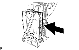
Engage the 2 claws to install the power management control ECU as shown in the illustration.
-
-
INSTALL ECU INTEGRATION BOX RH (for LHD)
-
Install the ECU integration box RH with the 2 nuts and bolt.
-
Engage the clamp to connect the wire harness.
-
Connect each connector.
-
-
INSTALL GLOVE COMPARTMENT DOOR ASSEMBLY (for LHD)
-
INSTALL LOWER NO. 2 INSTRUMENT PANEL AIRBAG ASSEMBLY (for LHD)
-
INSTALL NO. 2 INSTRUMENT PANEL UNDER COVER SUB-ASSEMBLY (for LHD)
-
INSTALL INSTRUMENT SIDE PANEL RH (for LHD)
-
INSTALL COWL SIDE TRIM SUB-ASSEMBLY RH (for LHD)
Tech Tips
Use the same procedure as for the LH side Click here.
-
INSTALL FRONT DOOR SCUFF PLATE RH (for LHD)
Tech Tips
Use the same procedure as for the LH side Click here.
-
INSTALL FRONT DOOR OPENING TRIM WEATHERSTRIP RH (for LHD)
Tech Tips
Use the same procedure as for the LH side Click here.
-
INSTALL POWER MANAGEMENT CONTROL ECU (for RHD)
-
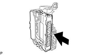
Engage the 2 claws to install the power management control ECU as shown in the illustration.
-
-
INSTALL ECU INTEGRATION BOX LH (for RHD)
-
Install the ECU integration box LH with the nut and bolt.
-
Engage the clamp to connect the wire harness.
-
Connect each connector.
-
-
INSTALL GLOVE COMPARTMENT DOOR ASSEMBLY (for RHD)
-
INSTALL LOWER NO. 2 INSTRUMENT PANEL AIRBAG ASSEMBLY (for RHD)
-
INSTALL NO. 2 INSTRUMENT PANEL UNDER COVER SUB-ASSEMBLY (for RHD)
-
INSTALL INSTRUMENT SIDE PANEL LH (for RHD)
-
INSTALL COWL SIDE TRIM SUB-ASSEMBLY LH (for RHD)
-
INSTALL FRONT DOOR SCUFF PLATE LH (for RHD)
-
INSTALL FRONT DOOR OPENING TRIM WEATHERSTRIP LH (for RHD)
-
CONNECT CABLE TO NEGATIVE BATTERY TERMINAL
Note
When disconnecting the cable, some systems need to be initialized after the cable is reconnected Click here.
-
INSTALL REAR FLOOR BOARD UPPER NO. 3 PLATE
-
INSTALL DECK FLOOR BOX RH
-
INSTALL REAR NO. 3 FLOOR BOARD
-
INSTALL REAR DECK FLOOR BOX
-
INSTALL REAR NO. 2 FLOOR BOARD
-
PERFORM DIAGNOSTIC SYSTEM CHECK
-
INSPECT SRS WARNING LIGHT