CAN COMMUNICATION SYSTEM TERMINALS OF ECU
Note
-
After turning the power switch off, waiting time may be required before disconnecting the cable from the negative (-) auxiliary battery terminal. Therefore, make sure to read the disconnecting the cable from the negative (-) auxiliary battery terminal notices before proceeding with work Click here.
-
Turn the power switch off before measuring the resistances between CAN main bus lines and between CAN branch lines.
-
Turn the power switch off before inspecting CAN bus lines for a ground short.
-
After the power switch is turned off, check that the key reminder warning system and light reminder warning system are not operating.
-
Before measuring the resistance, leave the vehicle as is for at least 1 minute and do not operate the power switch, any other switches or the doors. If any doors need to be opened in order to check connectors, open the doors and leave them open.
-
This section describes the standard values for all CAN related components.
Tech Tips
-
Operating the power switch, any other switches or a door triggers related ECU and sensor communication on the CAN. This communication will cause the resistance value to change.
-
Even after DTCs are cleared, if a DTC is stored again after driving the vehicle for a while, the malfunction may be occurring due to vibration of the vehicle. In such a case, wiggling the ECUs or wire harness while performing the inspection below may help determine the cause of the malfunction.
-
CAN NO. 1 JUNCTION CONNECTOR (for LHD)
-
Check the CAN No. 1 junction connector (Engine room main wire side).
Tech Tips
The following tables contain information about the items and buses connected via junction connectors. The junction connector may be used for multiple separate buses. In this case, the name of the bus will be shown below the name of the item that terminals are connected to. The bus name will be shown in brackets (example: (for Power management bus)).
-
Connection diagram
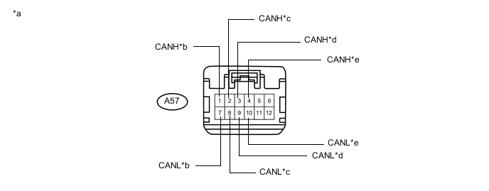
Text in Illustration *a Front view of wire harness connector
(to CAN No. 1 Junction Connector)
*b to ECM
(for V1 Bus)
*c to Skid Control ECU
(Brake Booster with Master Cylinder Assembly)
(for V1 Bus)
*d to Skid Control ECU
(Brake Booster with Master Cylinder Assembly)
(for Power Management Bus)
*e to ECM
(for Power Management Bus)
- - -
Check the connection diagram of the components which are connected to the CAN No. 1 junction connector.
Terminal No. (Symbol) Wiring Color Connected to (Applicable Bus) A57-1 (CANH) P ECM
(for V1 bus)
A57-7 (CANL) V A57-2 (CANH) LG Skid control ECU
(Brake booster with master cylinder assembly)
(for V1 bus)
A57-8 (CANL) L A57-3 (CANH) P Skid control ECU
(Brake booster with master cylinder assembly)
(for Power management bus)
A57-9 (CANL) V A57-4 (CANH) B ECM
(for Power management bus)
A57-10 (CANL) W
-
-
Check the CAN No. 1 junction connector (Instrument panel wire side).
-
Connection diagram
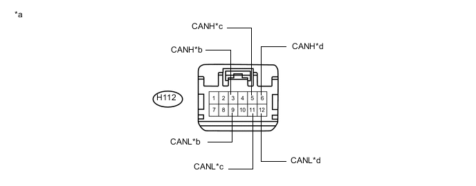
Text in Illustration *a Front view of wire harness connector
(to CAN No. 1 Junction Connector)
*b to CAN No. 5 Junction Connector
(for Power Management Bus)
*c Main body ECU
(Multiplex Network Body ECU)
(for V1 Bus)
*d to CAN No. 2 Junction Connector
(for V1 Bus)
-
Check the connection diagram of the components which are connected to the CAN No. 1 junction connector.
Terminal No. (Symbol) Wiring Color Connected to (Applicable Bus) H112-3 (CANH) B CAN No. 5 junction connector
(for Power management bus)
H112-9 (CANL) W H112-5 (CANH) BR Main body ECU
(Multiplex network body ECU)
(for V1 bus)
H112-11 (CANL) W H112-6 (CANH) R CAN No. 2 junction connector
(for V1 bus)
H112-12 (CANL) W
-
-
-
CAN NO. 1 JUNCTION CONNECTOR (for RHD)
-
Check the CAN No. 1 junction connector (Engine room main wire side).
-
Connection diagram
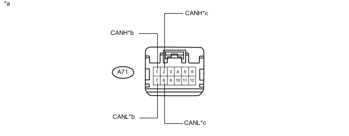
Text in Illustration *a Front view of wire harness connector
(to CAN No. 1 Junction Connector)
*b to ECM *c to Transmission Control ECU Assembly - - -
Check the connection diagram of the components which are connected to the CAN No. 1 junction connector.
Terminal No. (Symbol) Wiring Color Connected to A71-1 (CANH) P ECM A71-7 (CANL) V A71-2 (CANH) Y Transmission control ECU assembly A71-8 (CANL) BR
-
-
Check the CAN No. 1 junction connector (Instrument panel wire side).
-
Connection diagram
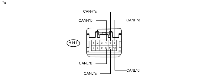
Text in Illustration *a Front view of wire harness connector
(to CAN No. 1 Junction Connector)
*b to Power Management Control ECU *c to Main body ECU
(Multiplex Network Body ECU)
*d to CAN No. 2 Junction Connector -
Check the connection diagram of the components which are connected to the CAN No. 1 junction connector.
Terminal No. (Symbol) Wiring Color Connected to H141-4 (CANH) P Power management control ECU H141-10 (CANL) V H141-5 (CANH) BR Main body ECU
(Multiplex network body ECU)
H141-11 (CANL) W H141-6 (CANH) R CAN No. 2 junction connector H141-12 (CANL) W
-
-
-
CAN NO. 2 JUNCTION CONNECTOR
-
Check the CAN No. 2 junction connector (Instrument panel connector holder front side).
-
Connection diagram
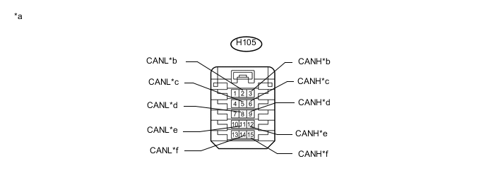
Text in Illustration *a Front view of wire harness connector
(to CAN No. 2 Junction Connector)
*b to Steering Angle Sensor
(Spiral Cable with Sensor Sub-assembly)
*c to Certification ECU
(Smart Key ECU Assembly)
*d to Airbag Sensor Assembly *e to Yaw Rate and Acceleration Sensor *f DCM (Telematics Transceiver)* *: w/ Manual (SOS) Switch
-
Check the connection diagram of the components which are connected to the CAN No. 2 junction connector.
Terminal No. (Symbol) Wiring Color Connected to H105-3 (CANH) L Steering angle sensor
(Spiral cable with sensor sub-assembly)
H105-2 (CANL) B H105-6 (CANH) L Certification ECU
(Smart key ECU assembly)
H105-5 (CANL) B H105-9 (CANH) L Airbag sensor assembly H105-8 (CANL) B H105-12 (CANH) L Yaw rate and acceleration sensor H105-11 (CANL) B H105-15 (CANH) R DCM (Telematics transceiver)* H105-14 (CANL) W *: w/ Manual (SOS) Switch
-
-
Check the CAN No. 2 junction connector (Instrument panel connector holder rear side).
-
Connection diagram
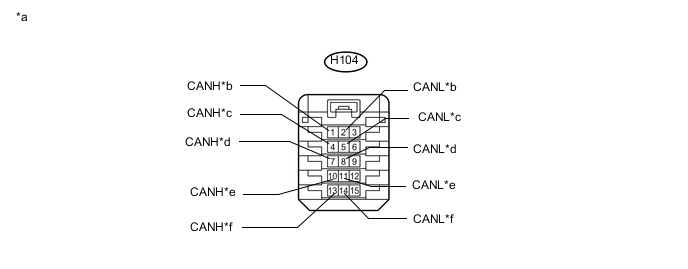
Text in Illustration *a Front view of wire harness connector
(to CAN No. 2 Junction Connector)
*b to CAN No. 1 Junction Connector *c to CAN No. 3 Junction Connector *d to DLC3 *e to Power Steering ECU Assembly *f to Radio Receiver Assembly*1*2 *1: for Navigation Receiver Type
*2: for Radio and Display Type
-
Check the connection diagram of the components which are connected to the CAN No. 2 junction connector.
Terminal No. (Symbol) Wiring Color Connected to H104-1 (CANH) R CAN No. 1 junction connector H104-2 (CANL) W H104-4 (CANH) R CAN No. 3 junction connector H104-5 (CANL) W H104-7 (CANH) R DLC3 H104-8 (CANL) W H104-10 (CANH) R Power steering ECU assembly H104-11 (CANL) W H104-13 (CANH) R Radio receiver assembly*1*2 H104-14 (CANL) W *1: for Navigation Receiver Type
*2: for Radio and Display Type
-
-
-
CAN NO. 3 JUNCTION CONNECTOR (for LHD)
-
Check the CAN No. 3 junction connector (Engine room main wire side).
-
Connection diagram
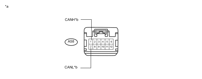
Text in Illustration *a Front view of wire harness connector
(to CAN No. 3 Junction Connector)
*b to Transmission Control ECU Assembly -
Check the connection diagram of the components which are connected to the CAN No. 3 junction connector.
Terminal No. (Symbol) Wiring Color Connected to A58-1 (CANH) Y Transmission control ECU assembly A58-7 (CANL) BR
-
-
Check the CAN No. 3 junction connector (Instrument panel wire side).
-
Connection diagram
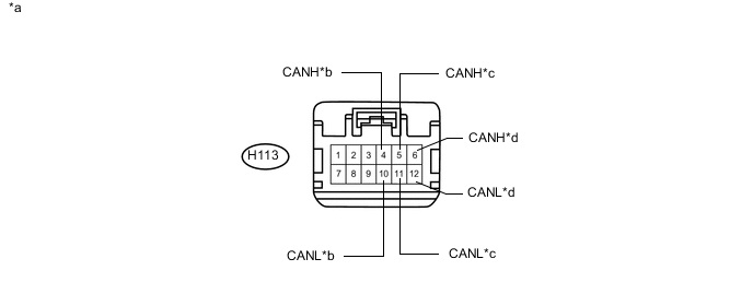
Text in Illustration *a Front view of wire harness connector
(to CAN No. 3 Junction Connector)
*b to Power Management Control ECU *c to CAN No. 2 Junction Connector *d to Combination Meter Assembly -
Check the connection diagram of the components which are connected to the CAN No. 3 junction connector.
Terminal No. (Symbol) Wiring Color Connected to H113-4 (CANH) P Power management control ECU H113-10 (CANL) V H113-5 (CANH) R CAN No. 2 junction connector H113-11 (CANL) W H113-6 (CANH) P Combination meter assembly H113-12 (CANL) V
-
-
-
CAN NO. 3 JUNCTION CONNECTOR (for RHD)
-
Check the CAN No. 3 junction connector (Engine room main wire side).
Tech Tips
The following tables contain information about the items and buses connected via junction connectors. The junction connector may be used for multiple separate buses. In this case, the name of the bus will be shown below the name of the item that terminals are connected to. The bus name will be shown in brackets (example: (for Power management bus)).
-
Connection diagram
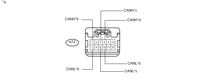
Text in Illustration *a Front view of wire harness connector
(to CAN No. 3 Junction Connector)
*b to Skid Control ECU
(Brake Booster with Master Cylinder Assembly)
(for V1 Bus)
*c to Skid Control ECU
(Brake Booster with Master Cylinder Assembly)
(for Power Management Bus)
*d to ECM
(for Power Management Bus)
-
Check the connection diagram of the components which are connected to the CAN No. 3 junction connector.
Terminal No. (Symbol) Wiring Color Connected to (Applicable Bus) A72-1 (CANH) LG Skid control ECU
(Brake booster with master cylinder assembly)
(for V1 bus)
A72-7 (CANL) L A72-3 (CANH) P Skid control ECU
(Brake booster with master cylinder assembly)
(for Power management bus)
A72-9 (CANL) V A72-4 (CANH) B ECM
(for Power management bus)
A72-10 (CANL) W
-
-
Check the CAN No. 3 junction connector (Instrument panel wire side).
-
Connection diagram
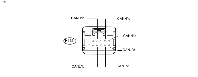
Text in Illustration *a Front view of wire harness connector
(to CAN No. 3 Junction Connector)
*b to CAN No. 5 Junction Connector
(for Power Management Bus)
*c to CAN No. 2 Junction Connector
(for V1 Bus)
*d to Combination Meter Assembly
(for V1 Bus)
-
Check the connection diagram of the components which are connected to the CAN No. 3 junction connector.
Terminal No. (Symbol) Wiring Color Connected to (Applicable Bus) H142-3 (CANH) B CAN No. 5 junction connector
(for Power management bus)
H142-9 (CANL) W H142-5 (CANH) R CAN No. 2 junction connector
(for V1 bus)
H142-11 (CANL) W H142-6 (CANH) P Combination meter assembly
(for V1 bus)
H142-12 (CANL) V
-
-
-
CAN NO. 4 JUNCTION CONNECTOR (for V2 Bus)
-
Check the CAN No. 4 junction connector.
-
Connection diagram
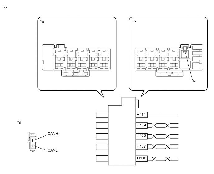
Text in Illustration *1 CAN No. 4 Junction Connector - - *a Junction Connector B Side *b Junction Connector A Side *c Ground Terminal *d Front view of wire harness connector
(to CAN No. 4 Junction Connector)
-
-
Check the connection diagram of the components which are connected to the CAN No. 4 junction connector.
Junction Connector A Side Terminal No. (Symbol) Wiring Color Connected to H111-1 (GND) W-B Body ground H106-1 (CANH) B*3
R*4
Power management control ECU*1
CAN No. 7 Junction Connector*2
H106-2 (CANL) W*3
B*4
H107-1 (CANH) G Clearance warning ECU assembly H107-2 (CANL) B H108-1 (CANH) L Driving support ECU assembly H108-2 (CANL) B H109-1 (CANH) Y Seat belt control ECU H109-2 (CANL) B *1: w/o Parking Assist Monitor System (w/o Parallel Parking Assist Function)
*2: w/ Parking Assist Monitor System (w/o Parallel Parking Assist Function)
*3: for LHD
*4: for RHD
-
-
CAN NO. 5 JUNCTION CONNECTOR (for Power Management Bus)
-
Check the CAN No. 5 junction connector (Instrument panel connector holder front side).
-
Connection diagram
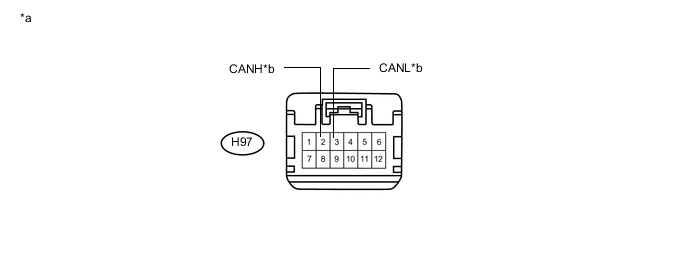
Text in Illustration *a Front view of wire harness connector
(to CAN No. 5 Junction Connector)
*b to CAN No. 1 Junction Connector (for LHD)
to CAN No. 3 Junction Connector (for RHD)
-
Check the connection diagram of the components which are connected to the CAN No. 5 junction connector.
Terminal No. (Symbol) Wiring Color Connected to H97-2 (CANH) B CAN No. 1 junction connector*1
CAN No. 3 junction connector*2
H97-3 (CANL) W *1: for LHD
*2: for RHD
-
-
Check the CAN No. 5 junction connector (Instrument panel connector holder rear side).
-
Connection diagram
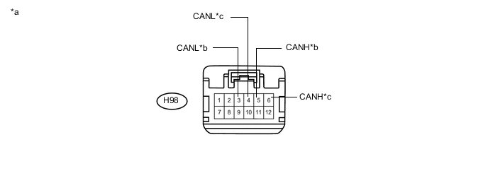
Text in Illustration *a Front view of wire harness connector
(to CAN No. 5 Junction Connector)
*b to Air Conditioning Amplifier Assembly *c to Power Management Control ECU - - -
Check the connection diagram of the components which are connected to the CAN No. 5 junction connector.
Terminal No. (Symbol) Wiring Color Connected to H98-5 (CANH) Y Air conditioning amplifier assembly H98-3 (CANL) BR H98-6 (CANH) LG Power management control ECU H98-4 (CANL) L
-
-
-
CAN NO. 6 JUNCTION CONNECTOR (for MS Bus)
-
Check the CAN No. 6 junction connector.
-
Connection diagram

Text in Illustration *1 CAN No. 6 Junction Connector - - *a Junction Connector B Side *b Junction Connector A Side *c Ground Terminal *d Front view of wire harness connector
(to CAN No. 6 Junction Connector)
-
-
Check the connection diagram of the components which are connected to the CAN No. 6 junction connector.
Junction Connector A Side Terminal No. (Symbol) Wiring Color Connected to H103-1 (GND) W-B Body ground H99-1 (CANH) R
-
Outer mirror control ECU assembly (Front passenger side)*1
-
Outer mirror control ECU assembly (Drive side)*2
H99-2 (CANL) W H100-1 (CANH) G Main body ECU
(Multiplex network body ECU)
H100-2 (CANL) W H101-1 (CANH) L Position control ECU and switch assembly H101-2 (CANL) W H102-1 (CANH) Y
-
Outer mirror control ECU assembly (Drive side)*1
-
Outer mirror control ECU assembly (Front passenger side)*2
H102-2 (CANL) W
-
*1: for LHD
-
*2: for RHD
-
-
-
CAN NO. 7 JUNCTION CONNECTOR (for V2 Bus)
-
Check the CAN No. 7 junction connector.
-
Connection diagram
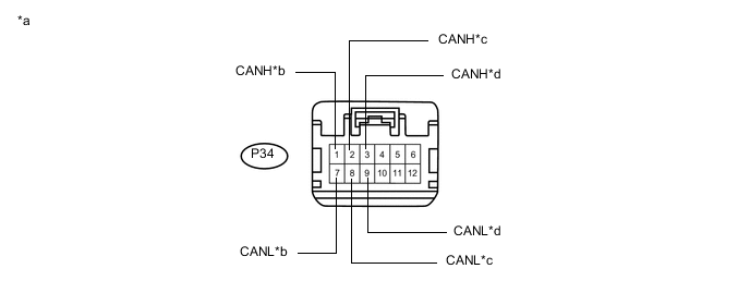
Text in Illustration *a Front view of wire harness connector
(to CAN No. 7 Junction Connector)
*b to CAN No. 4 Junction Connector *c to Rear Television Camera Assembly *d to Power Management Control ECU
-
-
Check the connection diagram of the components which are connected to the CAN No. 7 junction connector.
Terminal No. (Symbol) Wiring Color Connected to P34-1 (CANH) B CAN No. 4 junction connector P34-7 (CANL) W P34-2 (CANH) L Rear television camera assembly P34-8 (CANL) R P34-3 (CANH) BE Power management control ECU P34-9 (CANL) B
-
-
DLC3
-
Disconnect the cable from the negative (-) auxiliary battery terminal.
-
Measure the resistance according to the value(s) in the table below.
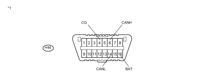
Text in Illustration *1 DLC3 - -
-
-
ECM
-
Disconnect the cable from the negative (-) auxiliary battery terminal.
-
Disconnect the A60 and D27 ECM connectors.
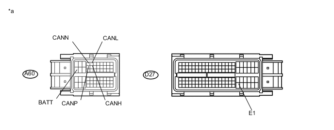
Text in Illustration *a Front view of wire harness connector
(to ECM)
- - -
Measure the resistance according to the value(s) in the table below.
-
-
COMBINATION METER ASSEMBLY
-
Disconnect the cable from the negative (-) auxiliary battery terminal.
-
Disconnect the H19 combination meter assembly connector.
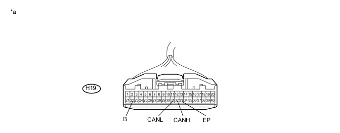
Text in Illustration *a Front view of wire harness connector
(to Combination Meter Assembly)
- - -
Measure the resistance according to the value(s) in the table below.
-
-
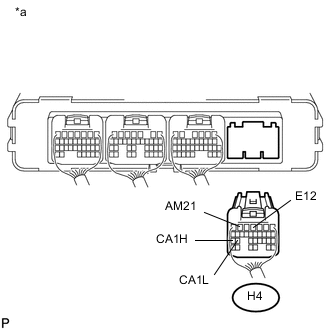
POWER MANAGEMENT CONTROL ECU
Text in Illustration *a Component without harness connected
(Power Management Control ECU)
- -
-
V1 Bus Branch Lines
-
Disconnect the cable from the negative (-) auxiliary battery terminal.
-
Text in Illustration *a Rear view of wire harness connector
(to Power Management Control ECU)
Disconnect the H4 power management control ECU connector.
-
Measure the resistance according to the value(s) in the table below.
-
-
V2 Bus Main Lines
-
Disconnect the cable from the negative (-) auxiliary battery terminal.
-
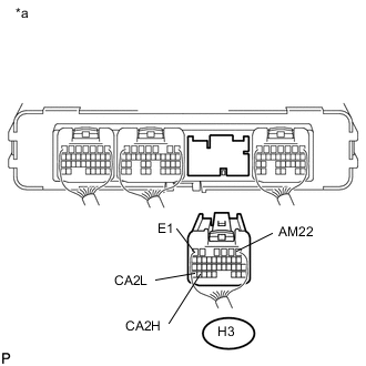
Text in Illustration *a Rear view of wire harness connector
(to Power Management Control ECU)
Disconnect the H3 power management control ECU connector.
-
Measure the resistance according to the value(s) in the table below.
-
-
Power Management Bus Main Lines
-
Disconnect the cable from the negative (-) auxiliary battery terminal.
-
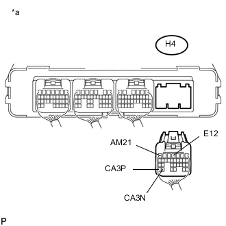
Text in Illustration *a Rear view of wire harness connector
(to Power Management Control ECU)
Disconnect the H4 power management control ECU connector.
-
Measure the resistance according to the value(s) in the table below.
-
-
-
MAIN BODY ECU (MULTIPLEX NETWORK BODY ECU)
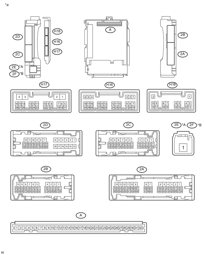
Text in Illustration *A for LHD *B for RHD *a Component without harness connected
(Main Body ECU (Multiplex Network Body ECU))
- -
-
Disconnect the cable from the negative (-) auxiliary battery terminal.
-
Disconnect the H16 and H17 main body ECU (multiplex network body ECU) connectors.
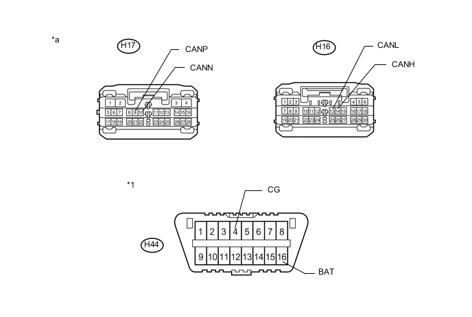
Text in Illustration *1 DLC3 - - *a Front view of wire harness connector
(to Main Body ECU (Multiplex Network Body ECU))
- - -
Measure the resistance according to the value(s) in the table below.
-
-
SKID CONTROL ECU (BRAKE BOOSTER WITH MASTER CYLINDER ASSEMBLY)
-
Disconnect the cable from the negative (-) auxiliary battery terminal.
-
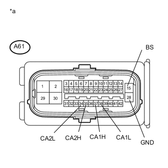
Text in Illustration *a Front view of wire harness connector
(to Skid Control ECU (Brake Booster with Master Cylinder Assembly))
Disconnect the A61 skid control ECU (brake booster with master cylinder assembly) connector.
-
Measure the resistance according to the value(s) in the table below.
-
-
STEERING ANGLE SENSOR (SPIRAL CABLE WITH SENSOR SUB-ASSEMBLY)
-
Disconnect the cable from the negative (-) auxiliary battery terminal.
-
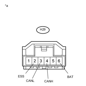
Text in Illustration *a Front view of wire harness connector
(to Steering Angle Sensor (Spiral Cable with Sensor Sub-assembly))
Disconnect the H29 steering angle sensor (spiral cable with sensor sub-assembly) connector.
-
Measure the resistance according to the value(s) in the table below.
-
-
YAW RATE AND ACCELERATION SENSOR
-
Disconnect the cable from the negative (-) auxiliary battery terminal.
-
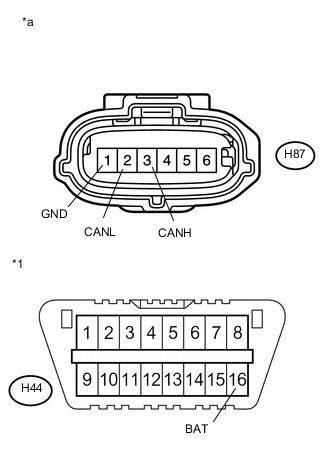
Text in Illustration *1 DLC3 *a Front view of wire harness connector
(to Yaw Rate and Acceleration Sensor)
Disconnect the H87 yaw rate and acceleration sensor connector.
-
Measure the resistance according to the value(s) in the table below.
-
-
POWER STEERING ECU ASSEMBLY
-
Disconnect the cable from the negative (-) auxiliary battery terminal.
-
Disconnect the H25 and A26 power steering ECU assembly connectors.
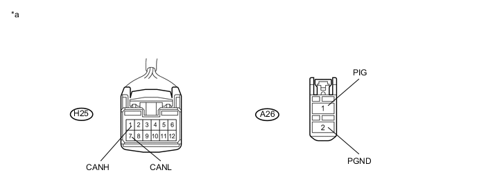
Text in Illustration *a Front view of wire harness connector
(to Power Steering ECU Assembly)
- - -
Measure the resistance according to the value(s) in the table below.
-
-
AIRBAG SENSOR ASSEMBLY
-
Disconnect the cable from the negative (-) auxiliary battery terminal.
-
Disconnect the H84 airbag sensor assembly connector.
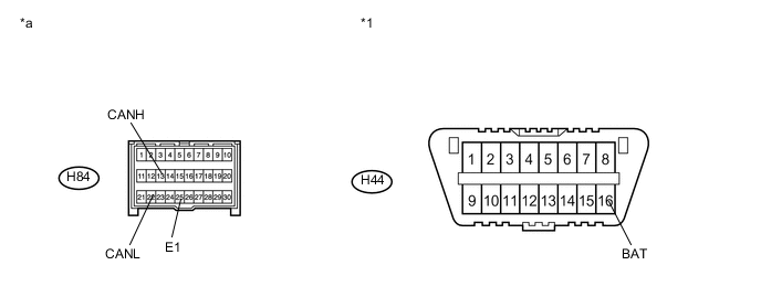
Text in Illustration *1 DLC3 - - *a Front view of wire harness connector
(to Airbag Sensor Assembly)
- - -
Measure the resistance according to the value(s) in the table below.
-
-
CERTIFICATION ECU (SMART KEY ECU ASSEMBLY)
-
Disconnect the cable from the negative (-) auxiliary battery terminal.
-
Disconnect the H1 certification ECU (smart key ECU assembly) connector.
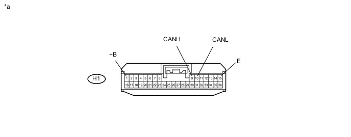
Text in Illustration *a Front view of wire harness connector
(to Certification ECU (Smart Key ECU Assembly))
- - -
Measure the resistance according to the value(s) in the table below.
-
-
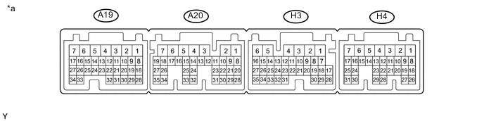
TRANSMISSION CONTROL ECU ASSEMBLY
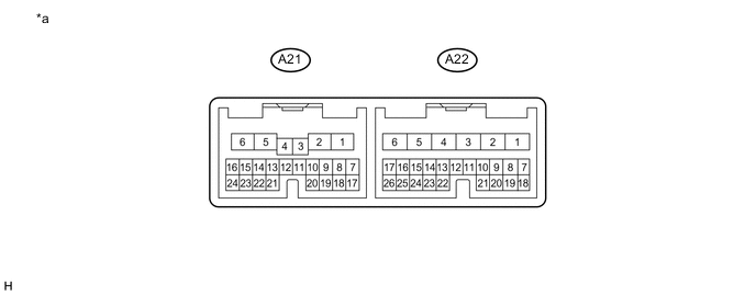
Text in Illustration *a Component without harness connected
(Transmission Control ECU Assembly)
- -
-
Disconnect the cable from the negative (-) auxiliary battery terminal.
-
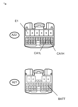
Text in Illustration *a Front view of wire harness connector
(to Transmission Control ECU Assembly)
Disconnect the A21 and A22 transmission control ECU assembly connectors.
-
Measure the resistance according to the value(s) in the table below.
-
-
RADIO RECEIVER ASSEMBLY (for Navigation receiver type)
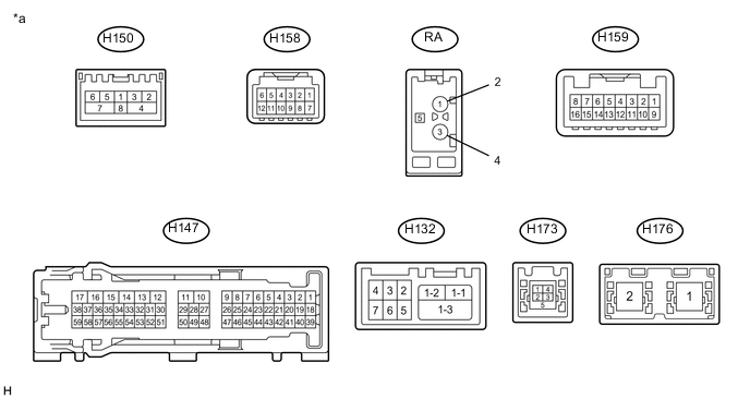
Text in Illustration *a Component without harness connected
(Radio Receiver Assembly)
- -
-
Disconnect the cable from the negative (-) auxiliary battery terminal.
-
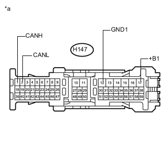
Text in Illustration *a Front view of wire harness connector
(to Radio Receiver Assembly)
Disconnect the H147 radio receiver assembly connector.
-
Measure the resistance according to the value(s) in the table below.
-
-
RADIO RECEIVER ASSEMBLY (for Radio and Display Type)
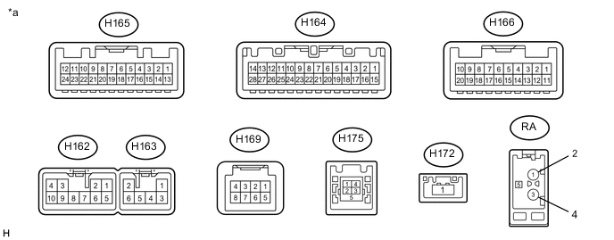
Text in Illustration *a Component without harness connected
(Radio Receiver Assembly)
- -
-
Disconnect the cable from the negative (-) auxiliary battery terminal.
-
Disconnect the H164 and H162 radio receiver assembly connectors.
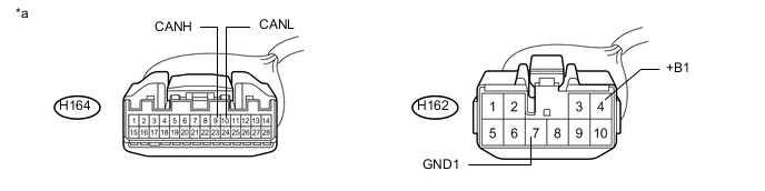
Text in Illustration *a Front view of wire harness connector
(to Radio Receiver Assembly)
- - -
Measure the resistance according to the value(s) in the table below.
-
-
AIR CONDITIONING AMPLIFIER ASSEMBLY
-
Disconnect the cable from the negative (-) auxiliary battery terminal.
-
Disconnect the H85 air conditioning amplifier assembly connector.
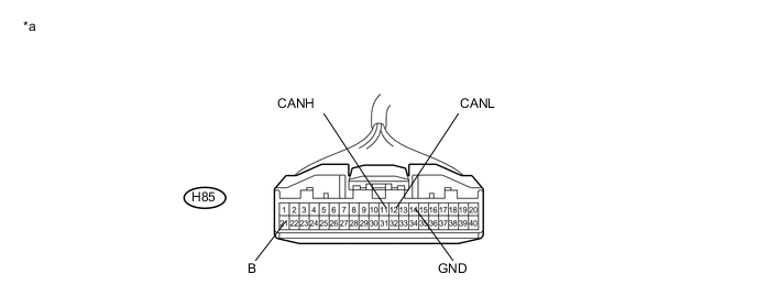
Text in Illustration *a Front view of wire harness connector
(to Air Conditioning Amplifier Assembly)
- - -
Measure the resistance according to the value(s) in the table below.
-
-
SEAT BELT CONTROL ECU (w/ Pre-crash Safety System)
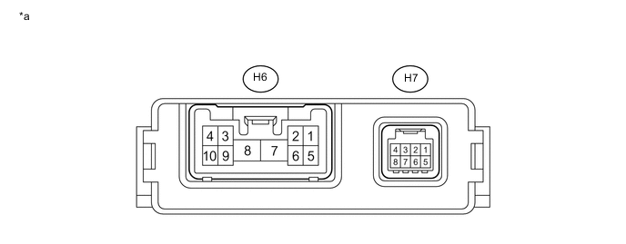
Text in Illustration *a Component without harness connected
(Seat Belt Control ECU)
- -
-
Disconnect the cable from the negative (-) auxiliary battery terminal.
-
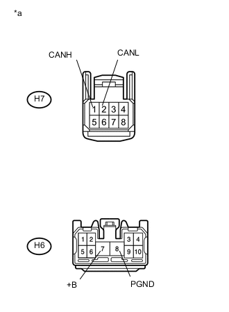
Text in Illustration *a Front view of wire harness connector
(to Seat Belt Control ECU)
Disconnect the H6 and H7 seat belt control ECU connectors.
-
Measure the resistance according to the value(s) in the table below.
-
-
DRIVING SUPPORT ECU ASSEMBLY (w/ Pre-crash Safety System)
-
Disconnect the cable from the negative (-) auxiliary battery terminal.
-
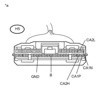
Text in Illustration *a Front view of wire harness connector
(to Driving Support ECU Assembly)
Disconnect the H5 driving support ECU assembly connector.
-
Measure the resistance according to the value(s) in the table below.
-
-
MILLIMETER WAVE RADAR SENSOR ASSEMBLY (w/ Pre-crash Safety System)
-
Disconnect the cable from the negative (-) auxiliary battery terminal.
-
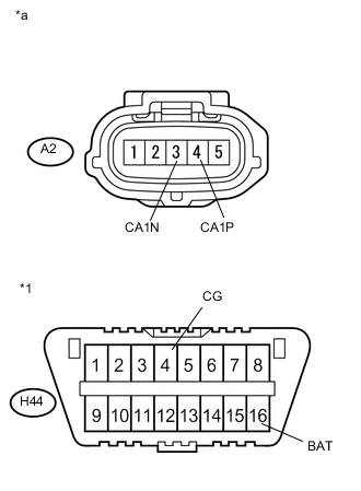
Text in Illustration *1 DLC3 *a Front view of wire harness connector
(to Millimeter Wave Radar Sensor Assembly)
Disconnect the A2 millimeter wave radar sensor assembly connector.
-
Measure the resistance according to the value(s) in the table below.
-
-
OUTER MIRROR CONTROL ECU ASSEMBLY (Driver side)
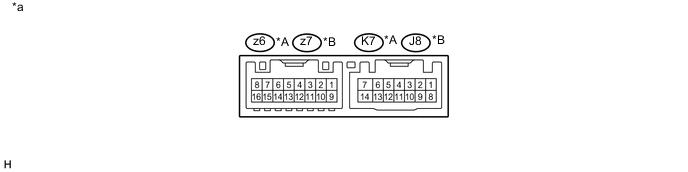
Text in Illustration *A for LHD *B for RHD *a Component without harness connected
(Outer Mirror Control ECU Assembly)
- -
-
Disconnect the cable from the negative (-) auxiliary battery terminal.
-
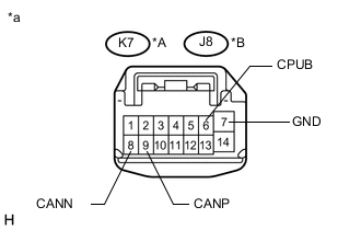
Text in Illustration *A for LHD *B for RHD *a Front view of wire harness connector
(to Outer Mirror Control ECU Assembly)
Disconnect the K7 or J8 outer mirror control ECU assembly connector.
-
Measure the resistance according to the value(s) in the table below.
-
-
OUTER MIRROR CONTROL ECU ASSEMBLY (Front passenger side)

Text in Illustration *A for RHD *B for LHD *a Component without harness connected
(Outer Mirror Control ECU Assembly)
- -
-
Disconnect the cable from the negative (-) auxiliary battery terminal.
-
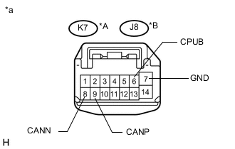
Text in Illustration *A for RHD *B for LHD *a Front view of wire harness connector
(to Outer Mirror Control ECU Assembly)
Disconnect the K7 or J8 outer mirror control ECU assembly connector.
-
Measure the resistance according to the value(s) in the table below.
-
-
POSITION CONTROL ECU AND SWITCH ASSEMBLY (w/ Seat Position Memory for LHD)

Text in Illustration *a Component without harness connected
(Position Control ECU and Switch Assembly)
- -
-
Disconnect the cable from the negative (-) auxiliary battery terminal.
-
Disconnect the X4 and X5 position control ECU and switch assembly connectors.
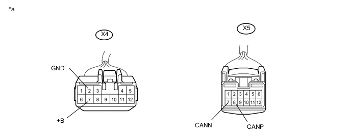
Text in Illustration *a Front view of wire harness connector
(to Position Control ECU and Switch Assembly)
- - -
Measure the resistance according to the value(s) in the table below.
-
-
POSITION CONTROL ECU AND SWITCH ASSEMBLY (w/ Seat Position Memory for RHD)

Text in Illustration *a Component without harness connected
(Position Control ECU and Switch Assembly)
- -
-
Disconnect the cable from the negative (-) auxiliary battery terminal.
-
Disconnect the W3 and W4 position control ECU and switch assembly connectors.
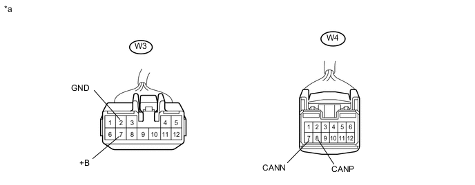
Text in Illustration *a Front view of wire harness connector
(to Position Control ECU and Switch Assembly)
- - -
Measure the resistance according to the value(s) in the table below.
-
-
CLEARANCE WARNING ECU ASSEMBLY (w/ LEXUS Parking Assist-sensor System)

Text in Illustration *a Component without harness connected
(Clearance Warning ECU Assembly)
- -
-
Disconnect the cable from the negative (-) auxiliary battery terminal.
-
Disconnect the A78 clearance warning ECU assembly connector.
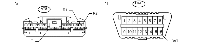
Text in Illustration *1 DLC3 - - *a Front view of wire harness connector
(to Clearance Warning ECU Assembly)
- - -
Measure the resistance according to the value(s) in the table below.
-
-
DCM (TELEMATICS TRANSCEIVER) (w/ Manual (SOS) Switch)
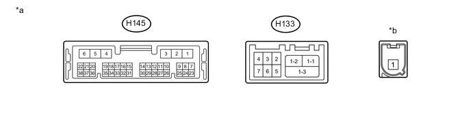
Text in Illustration *a Component without harness connected
(DCM (Telematics Transceiver))
*b Connect to telephone antenna connector
-
Disconnect the cable from the negative (-) auxiliary battery terminal.
-
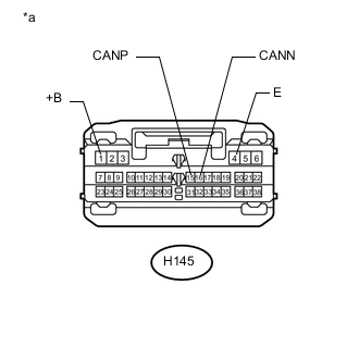
Text in Illustration *a Front view of wire harness connector
(to DCM (Telematics Transceiver))
Disconnect the H145 DCM (telematics transceiver) connector.
-
Measure the resistance according to the value(s) in the table below.
-
-
REAR TELEVISION CAMERA ASSEMBLY (w/ Parking Assist Monitor System (w/o Parallel Parking Assist Function))
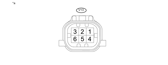
Text in Illustration *a Component without harness connected
(Rear Television Camera Assembly)
- -
-
Disconnect the cable from the negative (-) auxiliary battery terminal.
-
Disconnect the V13 rear television camera assembly connector.
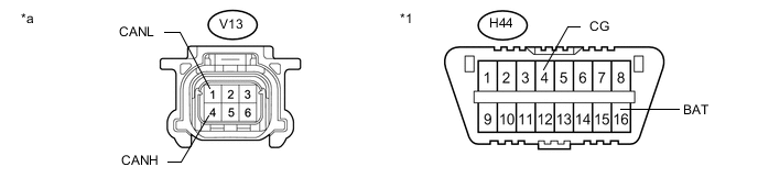
Text in Illustration *1 DLC3 - - *a Front view of wire harness connector
(to Rear Television Camera Assembly)
- - -
Measure the resistance according to the value(s) in the table below.
-