ELECTRONICALLY CONTROLLED BRAKE SYSTEM TERMINALS OF ECU
-
TERMINALS OF ECU
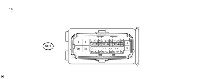
Text in Illustration *a Component without harness connected
(Skid Control ECU)
- - Terminal No. (Symbol) Terminal Description 1 (MRI1) Motor power supply input 1 2 (MRI2) Motor power supply input 2 3 (STP0) Stop light control relay output 4 (TS) Sensor check switch input 5 (FR-) Front speed sensor RH (-) signal input 6 (STP2) Stop light switch input 7 (RL-) Rear speed sensor LH (-) signal input 8 (CSW) Combination switch (Traction control switch) input 9 (RR-) Rear speed sensor RH (-) signal input 10 (HZRI) Hazard warning switch input 11 (SP1) Speed sensor signal output 12 (IG2) IG2 power source input 13 (BZ)*1 Skid control buzzer output 14 (BI) +B power source input 15 (BS) Solenoid power supply input 16 (IG1) IG1 power source input 17 - (Not used) 18 (FR+) Front speed sensor RH (+) power supply output 19 (CTY) Courtesy switch input 20 (RL+) Rear speed sensor LH (+) power supply output 21 (EXO) Stop light control relay output 22 (RR+) Rear speed sensor RH (+) power supply output 23 (GND6) Skid control ECU ground 6 24 (GND5) Skid control ECU ground 5 25 (GND4) Skid control ECU ground 4 26 (GND3) Skid control ECU ground 3 27 (GND2) Skid control ECU ground 2 28 (GND) Skid control ECU ground 29 (MRO1) Motor power supply output 1 30 (MRO2) Motor power supply output 2 31 (FL+) Front speed sensor LH (+) power supply output 32 (FL-) Front speed sensor LH (-) signal input 33 (STP) Stop light control relay input 34 (CA2L) CAN communication line 2 (L) 35 (CA2H) CAN communication line 2 (H) 36 (LBL) Brake fluid level warning switch input 37 (CA1H) CAN communication line 1 (H) 38 (CA1L) CAN communication line 1 (L) 39 (VCSK) Stroke sensor power supply output 40 (SKS2) Stroke sensor signal input 2 41 (SKG) Stroke sensor ground 42 (SKS) Stroke sensor signal input *1: w/ Dynamic Radar Cruise Control System
-
TERMINAL INSPECTION
-
Disconnect the connector and measure the voltage or resistance on the wire harness side.
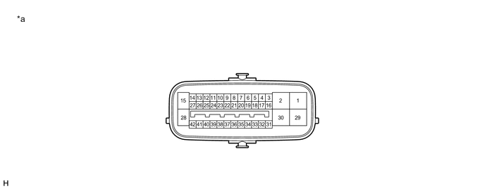
Text in Illustration *a Front view of wire harness connector
(to Skid Control ECU)
- - Tech Tips
Voltage cannot be measured with the connector connected to the skid control ECU as the connector is watertight.
Standard Terminal No. (Symbol) Wiring Color Terminal Description Condition Specified Condition A61-1 (MRI1) - Body ground B - Body ground Motor power supply input 1 Always 11 to 14 V A61-2 (MRI2) - Body ground R - Body ground Motor power supply input 2 Always 11 to 14 V A61-3 (STP0) - Body ground Y - Body ground Stop light control relay output Always 11 to 14 V A61-6 (STP2) - Body ground L - Body ground Stop light switch input Stop light switch ON → OFF
(Brake pedal depressed → released)
11 to 14 V → Below 1.5 V A61-8 (CSW) - Body ground R - Body ground Combination switch (Traction control switch) input Traction control switch ON → OFF (Pressed → not pressed) Below 1 Ω → 10 kΩ or higher A61-10 (HZRI) - Body ground SB - Body ground Hazard warning switch input Hazard warning switch ON → OFF Below 1 Ω → 10 kΩ or higher A61-12 (IG2) - Body ground BE - Body ground IG2 power source input Power switch on (IG) 11 to 14 V A61-13 (BZ) - Body ground*1 BR - Body ground Skid control buzzer output Power switch on (IG), buzzer not sounding 11 to 14 V A61-14 (BI) - Body ground W - Body ground +B power source input Always 11 to 14 V A61-15 (BS) - Body ground B - Body ground Solenoid power supply input Always 11 to 14 V A61-16 (IG1) - Body ground B - Body ground IG1 power source input Power switch on (IG) 11 to 14 V A61-19 (CTY) - Body ground V - Body ground Courtesy switch input Driver door close → open 11 to 14 V → Below 1.5 V A61-21 (EXO) - Body ground BE - Body ground Stop light control relay output Stop light switch ON → OFF
(Brake pedal depressed → released)
11 to 14 V → Below 1.5 V A61-23 (GND6) - Body ground W-B - Body ground Skid control ECU ground 6 Always Below 1 Ω A61-24 (GND5) - Body ground W-B - Body ground Skid control ECU ground 5 Always Below 1 Ω A61-25 (GND4) - Body ground W-B - Body ground Skid control ECU ground 4 Always Below 1 Ω A61-26 (GND3) - Body ground W-B - Body ground Skid control ECU ground 3 Always Below 1 Ω A61-27 (GND2) - Body ground W-B - Body ground Skid control ECU ground 2 Always Below 1 Ω A61-28 (GND) - Body ground W - Body ground Skid control ECU ground Always Below 1 Ω A61-33 (STP) - Body ground BE - Body ground Stop light control relay input Stop light switch ON → OFF
(Brake pedal depressed → released)
11 to 14 V → Below 1.5 V A61-36 (LBL) - Body ground P - Body ground Brake fluid level warning switch input Brake fluid level warning switch OFF → ON 1.84 to 2.16 kΩ → Below 1 Ω *1: w/ Dynamic Radar Cruise Control System
-