REAR LOWER ARM INSTALLATION

CAUTION / NOTICE / HINT
Tech Tips
-
Use the same procedure for the RH side and LH side.
-
The procedure listed below is for the LH side.
PROCEDURE
-
TEMPORARILY TIGHTEN REAR NO. 2 SUSPENSION ARM ASSEMBLY
-
Temporarily install the rear No. 2 suspension arm assembly to the rear suspension member sub-assembly with the bolt and nut.
Note
-
Since a stopper nut is used, turn the bolt.
-
Insert the bolt with the threaded end facing the front of the vehicle.
-
-
-
INSTALL REAR UPPER COIL SPRING INSULATOR
-
INSTALL REAR LOWER COIL SPRING INSULATOR
-
INSTALL REAR COIL SPRING
-
INSTALL REAR STABILIZER LINK ASSEMBLY
-
INSTALL REAR HEIGHT CONTROL SENSOR SUB-ASSEMBLY (w/ Height Control Sensor)
-
INSTALL REAR SUSPENSION MEMBER BRACE
-
TEMPORARILY TIGHTEN REAR NO. 1 SUSPENSION ARM ASSEMBLY
-
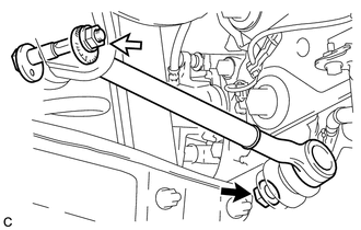
Temporarily tighten the rear No. 1 suspension arm assembly to the rear axle assembly with a new nut (A).
Text in Illustration 
Nut (A) 
Nut (B) -
Using the rear suspension toe adjust cam sub-assembly, No. 2 camber adjust cam and nut (B), temporarily install the rear No. 1 suspension arm assembly to the rear suspension member sub-assembly.
Note
-
Insert the rear suspension toe adjust cam sub-assembly from the rear of the vehicle.
-
Hold the rear suspension toe adjust cam sub-assembly while rotating the nut.
-
-
Fully tighten the nut (A).
- Torque:
- 100 N*m { 1020 kgf*cm, 74 ft.*lbf }
-
-
STABILIZE SUSPENSION
-
FULLY TIGHTEN REAR NO. 2 SUSPENSION ARM ASSEMBLY
-
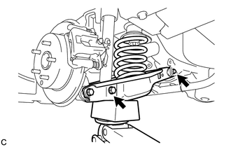
Fully tighten the 2 bolts.
- Torque:
- 90 N*m { 918 kgf*cm, 66 ft.*lbf }
Note
-
Since a stopper nut is used, turn the bolts.
-
Make sure that the rear No. 2 suspension arm assembly remains level when fully tightening the bolt.
-
-
INSTALL REAR FLOOR SIDE MEMBER COVER (w/ Floor Under Cover)
-
INSTALL REAR SUSPENSION ARM COVER
-
Insert the 2 claws of the rear suspension arm cover into the rear No. 2 suspension arm assembly.
-
Install the rear suspension arm cover with the 2 bolts.
- Torque:
- 12 N*m { 122 kgf*cm, 9 ft.*lbf }
Note
Make sure that the 2 claws of the rear suspension arm cover are inserted.
-
-
INSTALL REAR WHEEL
- Torque:
- 103 N*m { 1050 kgf*cm, 76 ft.*lbf }
-
FULLY TIGHTEN REAR NO. 1 SUSPENSION ARM ASSEMBLY
-
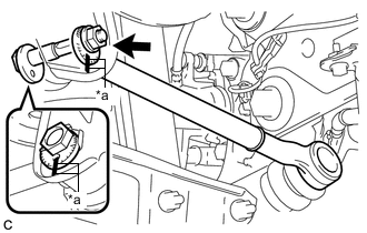
Text in Illustration *a Matchmarks Align the matchmarks on the No. 2 camber adjust cam, rear suspension toe adjust cam sub-assembly and rear suspension member sub-assembly.
-
Fully tighten the nut to install the rear No. 1 suspension arm assembly.
- Torque:
- 100 N*m { 1020 kgf*cm, 74 ft.*lbf }
Note
-
Hold the rear suspension toe adjust cam sub-assembly while rotating the nut.
-
Make sure that the vehicle is unloaded when fully tightening the nut.
-
-
INSPECT AND ADJUST REAR WHEEL ALIGNMENT
-
HEIGHT CONTROL SENSOR SIGNAL INITIALIZATION (w/ Height Control Sensor)
-
INSPECT AND ADJUST HEADLIGHT AIMING (w/ Height Control Sensor)