REAR SHOCK ABSORBER INSTALLATION
CAUTION / NOTICE / HINT
Tech Tips
-
Use the same procedure for the RH side and LH side.
-
The procedure listed below is for the LH side.
PROCEDURE
-
INSTALL REAR NO. 1 SPRING BUMPER
-
Install the rear No. 1 spring bumper to the rear shock absorber assembly.
-
-
TEMPORARILY TIGHTEN REAR SHOCK ABSORBER ASSEMBLY
-
Insert the upper end of the rear shock absorber assembly to the vehicle body.
-
Temporarily tighten the rear shock absorber assembly to the rear No. 2 suspension arm assembly with the bolt and nut.
Note
-
Since a stopper nut is used, turn the bolt.
-
Insert the bolt with the threaded end facing the front of the vehicle.
-
-
-
INSTALL REAR SUSPENSION SUPPORT
-
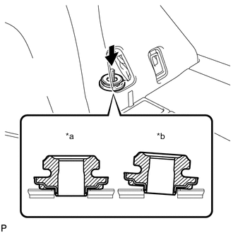
Text in Illustration *a Correct *b Incorrect Install the rear suspension support.
Note
Make sure that the rear suspension support is correctly installed as shown in the illustration.
-
-
INSTALL REAR SHOCK ABSORBER CUSHION RETAINER
-
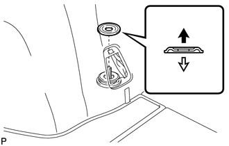
Install the rear shock absorber cushion retainer.
Text in Illustration 
Upper Side 
Lower Side Note
Be sure to install the rear shock absorber cushion retainer in the correct direction.
-
Apply a few drops of adhesive to the threads of a new nut.
Adhesive Toyota genuine adhesive 1324, three bond 1324 or equivalent -
Using a union nut wrench, fully tighten the nut while holding the rear shock absorber rod with a hexagon socket wrench.
- Torque:
- 25 N*m { 255 kgf*cm, 18 ft.*lbf }
Note
-
Securely insert the hexagon socket wrench to the rear shock absorber rod to prevent damage to the rear shock absorber assembly when tightening the nut.
-
Use the formula to calculate special torque values for situations where the union nut wrench is combined with a torque wrench Click here.
-
-
STABILIZE SUSPENSION
-
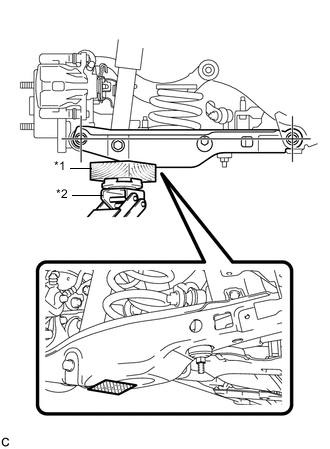
Text in Illustration *1 Wooden Block *2 Jack 
Wooden Block placement location Using a jack and wooden block as shown in the illustration, jack up the rear No. 2 suspension arm assembly to keep it level so that the suspension is positioned at the vehicle standard height position (position for final tightening of the suspension).
CAUTION:
Do not jack up the rear No. 2 suspension arm assembly too high as the vehicle may fall.
Note
-
When jacking up the rear No. 2 suspension arm assembly, be sure to jack it up slowly.
-
Make sure to perform this operation with the vehicle kept as low as possible.
Tech Tips
-
If the rear No. 2 suspension arm assembly cannot be positioned within the specification even when the rear No. 2 suspension arm assembly is jacked up, apply additional load such as by placing a weight in the luggage compartment.
-
This procedure duplicates standard vehicle height conditions.
-
Use the same procedure for the RH side and LH side.
-
-
-
FULLY TIGHTEN REAR SHOCK ABSORBER ASSEMBLY
-
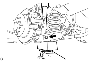
Fully tighten the bolt.
- Torque:
- 90 N*m { 918 kgf*cm, 66 ft.*lbf }
Note
-
Since a stopper nut is used, turn the bolt.
-
Make sure that the rear No. 2 suspension arm assembly remains level when fully tightening the bolt.
-
-
INSTALL REAR HEIGHT CONTROL SENSOR SUB-ASSEMBLY (w/ Height Control Sensor)
-
INSTALL REAR SUSPENSION ARM COVER
-
INSTALL REAR WHEEL
- Torque:
- 103 N*m { 1050 kgf*cm, 76 ft.*lbf }
-
INSTALL SIDE DECK TRIM SERVICE HOLE COVER
-
Engage the claw and 2 guides to install the side deck trim service hole cover.
-
-
HEIGHT CONTROL SENSOR SIGNAL INITIALIZATION (w/ Height Control Sensor)
-
INSPECT AND ADJUST HEADLIGHT AIMING (w/ Height Control Sensor)