REAR SUSPENSION MEMBER INSTALLATION

PROCEDURE
-
INSTALL REAR SUSPENSION MEMBER FRONT BODY MOUNTING CUSHION (for LH Side)
-
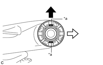
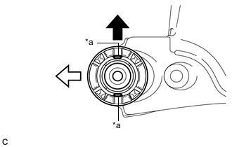
Text in Illustration *a Hole 
Front of the Vehicle 
Outside of the Vehicle Temporarily install a new rear suspension member front body mounting cushion so that the holes are positioned longitudinally as shown in the illustration.
-
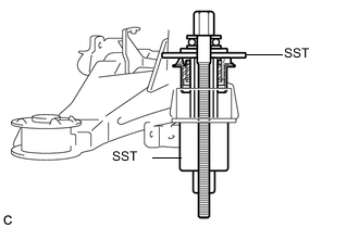
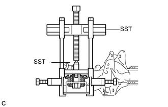
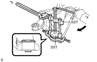
Install SST as shown in the illustration.
- SST
- 09570-24011
- 09830-10010 ( 09830-01010, 09830-01020, 09830-01040, 09830-01060 )
Note
Apply a small amount of grease to the threads of SST (center bolt) before use.
-
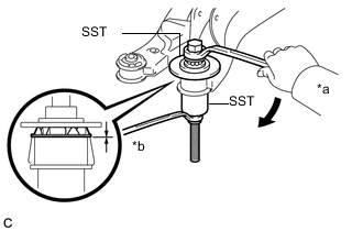
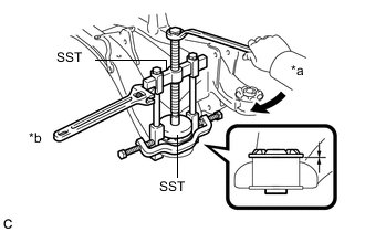
Text in Illustration *a Turn *b Hold Using SST, install the rear suspension member front body mounting cushion until there is no clearance between the rear suspension member sub-assembly and the rear suspension member front body mounting cushion.
- SST
- 09570-24011
- 09830-10010 ( 09830-01010, 09830-01020, 09830-01040, 09830-01060 )
Note
If the rear suspension member sub-assembly is scratched, apply paint to the scratched areas of the rear suspension member sub-assembly.
-
Remove SST from the rear suspension member sub-assembly.
-
-
INSTALL REAR SUSPENSION MEMBER FRONT BODY MOUNTING CUSHION (for RH Side)
Tech Tips
Perform the same procedure as the LH side.
-
INSTALL REAR SUSPENSION MEMBER REAR BODY MOUNTING CUSHION LH
-
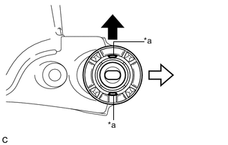
Text in Illustration *a Hole Front of the Vehicle Left Side of the Vehicle Temporarily install a new rear suspension member rear body mounting cushion LH so that the holes are positioned longitudinally as shown in the illustration.
-
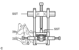
Install SST as shown in the illustration.
- SST
- 09950-40011 ( 09951-04020, 09952-04010, 09953-04030, 09954-04020, 09955-04051, 09957-04010, 09958-04011 )
- 09950-60020 ( 09951-00890, 09952-06010 )
Note
Apply a small amount of grease to the threads and tip of SST (center bolt) before use.
-
Text in Illustration *a Turn *b Hold Using SST, install the rear suspension member rear body mounting cushion LH until there is no clearance between the rear suspension member sub-assembly and the rear suspension member rear body mounting cushion LH.
- SST
- 09950-40011 ( 09951-04020, 09952-04010, 09953-04030, 09954-04020, 09955-04051, 09957-04010, 09958-04011 )
- 09950-60020 ( 09951-00890, 09952-06010 )
Note
If the rear suspension member sub-assembly is scratched, apply paint to the scratched areas of the rear suspension member sub-assembly.
-
Remove SST from the rear suspension member sub-assembly.
-
-
INSTALL REAR SUSPENSION MEMBER REAR BODY MOUNTING CUSHION RH
-
Text in Illustration *a Hole Front of the Vehicle Right Side of the Vehicle Temporarily install a new rear suspension member rear body mounting cushion RH so that the holes are positioned longitudinally as shown in the illustration.
-
Install SST as shown in the illustration.
- SST
- 09950-40011 ( 09951-04020, 09952-04010, 09953-04030, 09954-04020, 09955-04051, 09957-04010, 09958-04011 )
- 09950-60020 ( 09951-00890, 09952-06010 )
Note
Apply a small amount of grease to the threads and tip of SST (center bolt) before use.
-
Text in Illustration *a Turn *b Hold Using SST, install the rear suspension member rear body mounting cushion RH until there is no clearance between the rear suspension member sub-assembly and the rear suspension member rear body mounting cushion RH.
- SST
- 09950-40011 ( 09951-04020, 09952-04010, 09953-04030, 09954-04020, 09955-04051, 09957-04010, 09958-04011 )
- 09950-60020 ( 09951-00890, 09952-06010 )
Note
If the rear suspension member sub-assembly is scratched, apply paint to the scratched areas of the rear suspension member sub-assembly.
-
Remove SST from the rear suspension member sub-assembly.
-
-
INSTALL REAR UPPER CONTROL ARM ASSEMBLY LH
-
Temporarily install the rear upper control arm assembly LH to the rear suspension member sub-assembly with the bolt and nut.
Note
-
Since a stopper nut is used, turn the bolt.
-
Insert the bolt with the threaded end facing the rear of the vehicle.
-
-
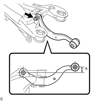
Set the rear upper control arm assembly LH in the tightening position as shown in the illustration.
Reference length (A) 23.0 mm (0.906 in.) -
Fully tighten the bolt in the tightening position.
- Torque:
- 90 N*m { 918 kgf*cm, 66 ft.*lbf }
Note
Since a stopper nut is used, turn the bolt.
-
-
INSTALL REAR UPPER CONTROL ARM ASSEMBLY RH
Tech Tips
Perform the same procedure as the LH side.
-
INSTALL REAR SUSPENSION MEMBER UPPER STOPPER
-
Install the 2 rear suspension member upper stoppers to the rear suspension member sub-assembly.
Note
Be sure to install the rear suspension member upper stoppers in the correct direction.
-
-
INSTALL REAR SUSPENSION MEMBER REAR UPPER STOPPER
-
Install the 2 rear suspension member rear upper stoppers to the rear suspension member sub-assembly.
Note
Be sure to install the rear suspension member rear upper stoppers in the correct direction.
-
-
INSTALL REAR SUSPENSION MEMBER SUB-ASSEMBLY
-
Support the rear suspension member sub-assembly with an engine lifter using 4 attachments or equivalent tools.
Note
-
Make sure to secure the rear suspension member sub-assembly to prevent it from dropping.
-
Use the attachments to keep the rear suspension member sub-assembly level.
-
The rear suspension member sub-assembly is a heavy component. Make sure that it is supported securely.
-
-
Raise the rear suspension member sub-assembly until there is no clearance between the rear suspension member sub-assembly and the body.
Note
When raising the rear suspension member sub-assembly, be careful not to damage the vehicle body or other components installed on the vehicle.
-
Install the rear suspension member sub-assembly with the 2 rear suspension member lower stoppers, 2 rear suspension member rear lower stoppers, 2 bolts, 2 nuts (A) and 2 nuts (B).
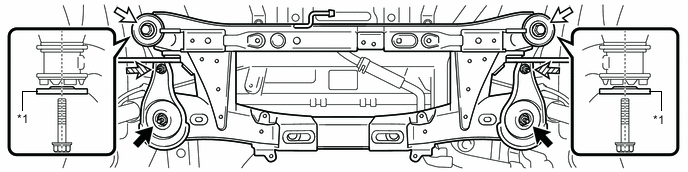
Text in Illustration *1 Rear Suspension Member Rear Lower Stopper - - Nut (A) Bolt 
Nut (B) - - - Torque:
- Bolt
- 125 N*m { 1275 kgf*cm, 92 ft.*lbf }
- Nut (A)
- 125 N*m { 1275 kgf*cm, 92 ft.*lbf }
- Nut (B)
- 61 N*m { 620 kgf*cm, 45 ft.*lbf }
Note
Be sure to install the rear suspension member sub-assembly with the rear suspension member rear lower stoppers facing in the correct direction as shown in the illustration.
-
Lower the engine lifter.
-
-
INSTALL REAR STABILIZER BAR
-
INSTALL REAR SUSPENSION MEMBER BRACE LH
-
INSTALL REAR SUSPENSION MEMBER BRACE RH
Tech Tips
Perform the same procedure as the LH side.
-
INSTALL REAR UPPER COIL SPRING INSULATOR LH
-
INSTALL REAR UPPER COIL SPRING INSULATOR RH
Tech Tips
Perform the same procedure as the LH side.
-
INSTALL REAR LOWER COIL SPRING INSULATOR LH
-
INSTALL REAR LOWER COIL SPRING INSULATOR RH
Tech Tips
Perform the same procedure as the LH side.
-
TEMPORARILY TIGHTEN REAR NO. 2 SUSPENSION ARM ASSEMBLY LH
-
Temporarily install the rear No. 2 suspension arm assembly LH to the rear suspension member sub-assembly with the bolt and nut.
Note
-
Since a stopper nut is used, turn the bolt.
-
Insert the bolt with the threaded end facing the front of the vehicle.
-
-
Set the rear coil spring LH to the rear No. 2 suspension arm assembly LH.
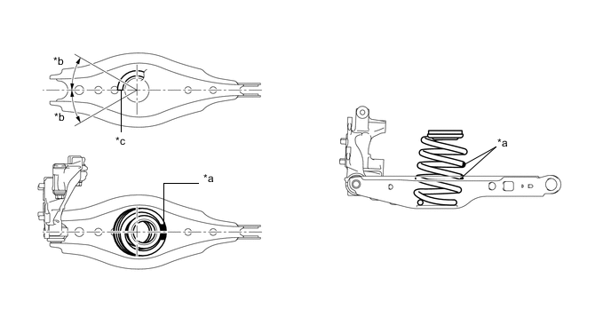
Text in Illustration *a Identification Mark *b 30° or less *c Lower End of Rear Coil Spring Note
-
Set the rear coil spring so that the identification marks are positioned as shown in the illustration.
-
Set the rear coil spring so that its lower end is within the range shown in the illustration.
-
-
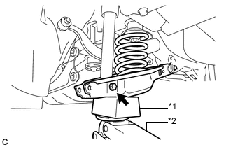
Text in Illustration *1 Wooden Block *2 Jack Using a jack and wooden block, slowly jack up the rear No. 2 suspension arm assembly LH.
CAUTION:
Do not jack up the rear No. 2 suspension arm assembly too high as the vehicle may fall.
Note
-
When jacking up the rear No. 2 suspension arm assembly, be sure to jack it up slowly.
-
Make sure to perform this operation with the vehicle kept as low as possible.
-
-
Temporarily install the rear No. 2 suspension arm assembly LH and rear coil spring LH with the bolt and nut.
Note
-
Since a stopper nut is used, turn the bolt.
-
Insert the bolt with the threaded end facing the front of the vehicle.
-
-
-
TEMPORARILY TIGHTEN REAR NO. 2 SUSPENSION ARM ASSEMBLY RH
Tech Tips
Perform the same procedure as the LH side.
-
INSTALL REAR STABILIZER LINK ASSEMBLY LH
-
INSTALL REAR STABILIZER LINK ASSEMBLY RH
Tech Tips
Perform the same procedure as the LH side.
-
INSTALL REAR AXLE ASSEMBLY (for LH Side)
-
Use a jack and wooden block to keep the rear No. 2 suspension arm assembly level.
CAUTION:
Do not jack up the rear No. 2 suspension arm assembly too high as the vehicle may fall.
Note
-
When jacking up the rear No. 2 suspension arm assembly, be sure to jack it up slowly.
-
Make sure to perform this operation with the vehicle kept as low as possible.
-
-
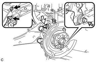
Text in Illustration *1 No. 2 Flexible Hose Bracket Bolt (A) Bolt (B) Bolt (C) Temporarily install the rear axle assembly to the rear No. 2 suspension arm assembly with the bolt (C) and nut.
Note
-
Insert the bolt with the threaded end facing the front of the vehicle.
-
Since a stopper nut is used, turn the bolt.
-
-
Temporarily install the rear axle assembly and No. 2 flexible hose bracket to the rear upper control arm assembly with the bolt (B) and nut.
Note
-
Insert the bolt with the threaded end facing the rear of the vehicle.
-
Since a stopper nut is used, turn the bolt.
-
-
Install the rear axle assembly to the rear trailing arm assembly with the 2 bolts (A).
- Torque:
- 200 N*m { 2039 kgf*cm, 148 ft.*lbf }
-
Fully tighten the bolt (B) and bolt (C).
- Torque:
- 90 N*m { 918 kgf*cm, 66 ft.*lbf }
Note
Since the stopper nuts are used, turn the bolts.
-
Slowly lower the rear No. 2 suspension arm assembly.
-
-
INSTALL REAR AXLE ASSEMBLY (for RH Side)
Tech Tips
Perform the same procedure as the LH side.
-
TEMPORARILY TIGHTEN REAR NO. 1 SUSPENSION ARM ASSEMBLY LH
-
TEMPORARILY TIGHTEN REAR NO. 1 SUSPENSION ARM ASSEMBLY RH
Tech Tips
Perform the same procedure as the LH side.
-
INSTALL REAR DISC
-
Install the 2 rear discs Click here.
-
-
INSTALL REAR DISC BRAKE CALIPER ASSEMBLY LH
-
INSTALL REAR DISC BRAKE CALIPER ASSEMBLY RH
Tech Tips
Perform the same procedure as the LH side.
-
CONNECT NO. 3 PARKING BRAKE CABLE ASSEMBLY
-
CONNECT NO. 2 PARKING BRAKE CABLE ASSEMBLY
Tech Tips
Perform the same procedure as for the No. 3 parking brake cable assembly.
-
INSTALL PARKING BRAKE LEVER PROTECTOR (for LH Side)
-
INSTALL PARKING BRAKE LEVER PROTECTOR (for RH Side)
Tech Tips
Perform the same procedure as the LH side.
-
INSTALL REAR HEIGHT CONTROL SENSOR SUB-ASSEMBLY (w/ Height Control Sensor)
-
INSTALL REAR SPEED SENSOR WIRE LH
-
INSTALL REAR SPEED SENSOR WIRE RH
Tech Tips
Perform the same procedure as the LH side.
-
ADJUST PARKING BRAKE
-
STABILIZE SUSPENSION
-
FULLY TIGHTEN REAR NO. 2 SUSPENSION ARM ASSEMBLY LH
-
FULLY TIGHTEN REAR NO. 2 SUSPENSION ARM ASSEMBLY RH
Tech Tips
Perform the same procedure as the LH side.
-
INSTALL REAR FLOOR SIDE MEMBER COVER (w/ Floor Under Cover)
-
for LH Side:
-
Install the rear floor side member cover LH with the 2 bolts, nut and 2 clips.
-
-
for RH Side:
-
Install the rear floor side member cover RH with the bolt, nut and 2 clips.
-
-
-
INSTALL REAR SUSPENSION ARM COVER LH
-
INSTALL REAR SUSPENSION ARM COVER RH
Tech Tips
Perform the same procedure as the LH side.
-
INSTALL TAIL EXHAUST PIPE ASSEMBLY
-
for 2ZR-FXE: Click here
-
for 5ZR-FXE: Click here
-
-
INSTALL REAR WHEELS
- Torque:
- 103 N*m { 1050 kgf*cm, 76 ft.*lbf }
-
FULLY TIGHTEN REAR NO. 1 SUSPENSION ARM ASSEMBLY LH
-
FULLY TIGHTEN REAR NO. 1 SUSPENSION ARM ASSEMBLY RH
Tech Tips
Perform the same procedure as the LH side.
-
INSTALL LOWER INSTRUMENT PANEL FINISH PANEL SUB-ASSEMBLY (for LHD)
-
INSTALL INSTRUMENT SIDE PANEL LH (for LHD)
-
INSTALL FRONT DOOR OPENING TRIM WEATHERSTRIP LH (for LHD)
-
INSTALL NO. 1 INSTRUMENT PANEL UNDER COVER SUB-ASSEMBLY (for LHD)
-
INSTALL NO. 2 AIR DUCT SUB-ASSEMBLY (for RHD)
-
INSTALL NO. 1 INSTRUMENT PANEL UNDER COVER SUB-ASSEMBLY (for RHD)
-
CONNECT CABLE TO NEGATIVE AUXILIARY BATTERY TERMINAL
-
Connect the cable to the negative (-) auxiliary battery terminal.
-
for 2ZR-FXE: Click here
-
for 5ZR-FXE: Click here
-
-
Connect the reservoir level switch connector.
-
Clear the DTCs Click here.
-
-
INSPECT AND ADJUST REAR WHEEL ALIGNMENT
-
HEIGHT CONTROL SENSOR SIGNAL INITIALIZATION (w/ Height Control Sensor)
-
INSPECT AND ADJUST HEADLIGHT AIMING (w/ Height Control Sensor)
-
CHECK FOR SPEED SENSOR SIGNAL