FRONT DRIVE SHAFT ASSEMBLY REMOVAL

CAUTION / NOTICE / HINT
Tech Tips
-
Use the same procedure for the RH side and LH side.
-
The procedure listed below is for the LH side.
PROCEDURE
-
REMOVE FRONT WHEELS
-
REMOVE NO. 1 ENGINE UNDER COVER
-
REMOVE REAR ENGINE UNDER COVER LH
-
REMOVE REAR ENGINE UNDER COVER RH
-
DRAIN HYBRID TRANSAXLE FLUID
-
REMOVE FRONT AXLE SHAFT NUT
-
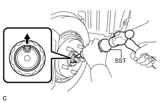
Using SST and a hammer, release the staked part of the front axle shaft nut.
- SST
- 09930-00010
Note
Loosen the staked part of the nut completely, otherwise the threads of the drive shaft may be damaged.
-
While applying the brakes, remove the front axle shaft nut.
-
-
SEPARATE FRONT SPEED SENSOR
-
SEPARATE FRONT FLEXIBLE HOSE
-
SEPARATE TIE ROD END SUB-ASSEMBLY
-
SEPARATE FRONT STABILIZER LINK ASSEMBLY
-
SEPARATE FRONT LOWER NO. 1 SUSPENSION ARM SUB-ASSEMBLY
-
SEPARATE FRONT DRIVE SHAFT ASSEMBLY
-
REMOVE FRONT DRIVE SHAFT ASSEMBLY
-
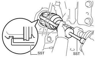
Using SST, remove the front drive shaft assembly.
- SST
- 09520-00031
- 09520-01010
Note
-
Do not damage the transaxle case oil seal.
-
Do not damage the inboard joint boot.
-
Do not drop the front drive shaft assembly.
-
-
REMOVE FRONT DRIVE SHAFT HOLE SNAP RING
-
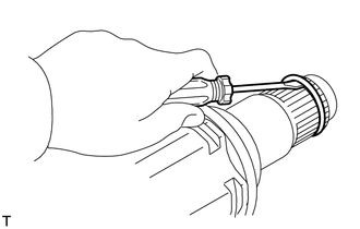
Using a screwdriver, remove the front drive shaft hole snap ring.
-