REAR AXLE CARRIER INSTALLATION
CAUTION / NOTICE / HINT
Tech Tips
-
Use the same procedure for the RH side and LH side.
-
The procedure listed below is for the LH side.
PROCEDURE
-
INSTALL REAR AXLE CARRIER SUB-ASSEMBLY
-
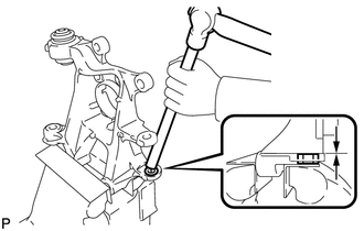
Hold the rear axle carrier sub-assembly between aluminum plates in a vise.
Note
Do not overtighten the vise.
-
Using a brass bar and a hammer, push out the bushing until it is positioned as shown in the illustration.
Tech Tips
Pushing out the bushing makes it easier to install the rear axle carrier sub-assembly.
-
Use a jack and wooden block to keep the rear No. 2 suspension arm assembly level.
CAUTION:
Do not jack up the rear No. 2 suspension arm assembly too high as the vehicle may fall.
Note
-
When jacking up the rear No. 2 suspension arm assembly, be sure to jack it up slowly.
-
Make sure to perform this operation with the vehicle kept as low as possible.
-
-
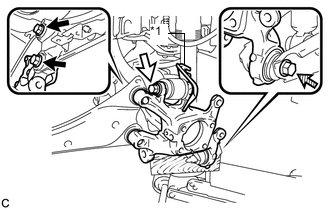
Text in Illustration *1 No. 2 Flexible Hose Bracket 
Bolt (A) 
Bolt (B) 
Bolt (C) Temporarily install the rear axle carrier sub-assembly to the rear No. 2 suspension arm assembly with the bolt (C) and nut.
Note
-
Insert the bolt with the threaded end facing the front of the vehicle.
-
Since a stopper nut is used, turn the bolt.
-
-
Temporarily install the rear axle carrier sub-assembly and No. 2 flexible hose bracket to the rear upper control arm assembly with the bolt (B) and nut.
Note
-
Insert the bolt with the threaded end facing the rear of the vehicle.
-
Since a stopper nut is used, turn the bolt.
-
-
Install the rear axle carrier sub-assembly to the rear trailing arm assembly with the 2 bolts (A).
- Torque:
- 200 N*m { 2039 kgf*cm, 148 ft.*lbf }
-
Fully tighten the bolt (B) and bolt (C).
- Torque:
- 90 N*m { 918 kgf*cm, 66 ft.*lbf }
Note
Since stopper nuts are used, turn the bolts.
-
Slowly lower the rear No. 2 suspension arm assembly.
-
-
TEMPORARILY TIGHTEN REAR NO. 1 SUSPENSION ARM ASSEMBLY
-
INSTALL REAR AXLE HUB AND BEARING ASSEMBLY
-
INSTALL REAR HEIGHT CONTROL SENSOR SUB-ASSEMBLY (w/ Height Control Sensor)
-
CONNECT REAR SPEED SENSOR WIRE
-
INSTALL REAR DISC
-
INSTALL REAR DISC BRAKE CALIPER ASSEMBLY
-
CONNECT NO. 3 PARKING BRAKE CABLE ASSEMBLY
-
INSTALL PARKING BRAKE LEVER PROTECTOR
-
ADJUST PARKING BRAKE
-
INSTALL LOWER INSTRUMENT PANEL FINISH PANEL SUB-ASSEMBLY (for LHD)
-
INSTALL INSTRUMENT SIDE PANEL LH (for LHD)
-
INSTALL FRONT DOOR OPENING TRIM WEATHERSTRIP LH (for LHD)
-
INSTALL NO. 1 INSTRUMENT PANEL UNDER COVER SUB-ASSEMBLY (for LHD)
-
INSTALL NO. 2 AIR DUCT SUB-ASSEMBLY (for RHD)
-
INSTALL NO. 1 INSTRUMENT PANEL UNDER COVER SUB-ASSEMBLY (for RHD)
-
INSTALL REAR FLOOR SIDE MEMBER COVER (w/ Floor Under Cover)
-
INSTALL REAR SUSPENSION ARM COVER
-
INSTALL REAR WHEEL
- Torque:
- 103 N*m { 1050 kgf*cm, 76 ft.*lbf }
-
FULLY TIGHTEN REAR NO. 1 SUSPENSION ARM ASSEMBLY
-
CONNECT CABLE TO NEGATIVE AUXILIARY BATTERY TERMINAL
-
Connect the cable to the negative (-) auxiliary battery terminal.
-
for 2ZR-FXE: Click here
-
for 5ZR-FXE: Click here
-
-
Connect the reservoir level switch connector.
-
Clear the DTCs Click here.
-
-
INSPECT AND ADJUST REAR WHEEL ALIGNMENT
-
HEIGHT CONTROL SENSOR SIGNAL INITIALIZATION (w/ Height Control Sensor)
-
INSPECT AND ADJUST HEADLIGHT AIMING (w/ Height Control Sensor)
-
CHECK FOR SPEED SENSOR SIGNAL