HYBRID VEHICLE TRANSAXLE REMOVAL
PROCEDURE
-
PRECAUTION
Note
After turning the power switch off, waiting time may be required before disconnecting the cable from the negative (-) auxiliary battery terminal. Therefore, make sure to read the disconnecting the cable from the negative (-) auxiliary battery terminal notices before proceeding with work Click here.
-
REMOVE REAR NO. 2 FLOOR BOARD
-
REMOVE REAR DECK FLOOR BOX
-
REMOVE REAR NO. 3 FLOOR BOARD
-
REMOVE DECK FLOOR BOX RH
-
REMOVE REAR FLOOR BOARD UPPER NO. 3 PLATE
-
DISCONNECT CABLE FROM NEGATIVE AUXILIARY BATTERY TERMINAL
Note
When disconnecting the cable, some systems need to be initialized after the cable is reconnected Click here.
-
REMOVE SERVICE PLUG GRIP
-
REMOVE HOOD SUB-ASSEMBLY
-
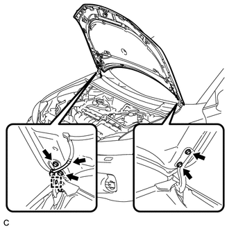
Disconnect the washer hose.
-
Disengage the clamp.
-
Remove the 4 bolts and hood sub-assembly.
-
-
ALIGN FRONT WHEELS FACING STRAIGHT AHEAD
-
REMOVE FRONT WHEEL
-
REMOVE REAR ENGINE UNDER COVER LH (for 2ZR-FXE)
-
REMOVE REAR ENGINE UNDER COVER LH (for 5ZR-FXE)
-
REMOVE REAR ENGINE UNDER COVER RH (for 2ZR-FXE)
-
REMOVE REAR ENGINE UNDER COVER RH (for 5ZR-FXE)
-
REMOVE FRONT LOWER BUMPER ABSORBER (for 2ZR-FXE)
-
REMOVE FRONT LOWER BUMPER ABSORBER (for 5ZR-FXE)
-
REMOVE NO. 1 ENGINE UNDER COVER (for 2ZR-FXE)
-
REMOVE NO. 1 ENGINE UNDER COVER (for 5ZR-FXE)
-
DRAIN COOLANT (for Engine)
for 2ZR-FXE Click here
for 5ZR-FXE Click here
-
DRAIN COOLANT (for Inverter)
-
DRAIN HYBRID TRANSAXLE FLUID
-
REMOVE WINDSHIELD WIPER MOTOR AND LINK ASSEMBLY
-
REMOVE NO. 1 HEATER AIR DUCT SPLASH SHIELD SEAL (for LHD)
-
REMOVE NO. 1 HEATER AIR DUCT SPLASH SHIELD SEAL (for RHD)
-
REMOVE NO. 2 HEATER AIR DUCT SPLASH SHIELD SEAL (for LHD)
-
REMOVE NO. 2 HEATER AIR DUCT SPLASH SHIELD SEAL (for RHD)
-
REMOVE COWL BODY MOUNTING REINFORCEMENT LH (for LHD)
-
REMOVE COWL BODY MOUNTING REINFORCEMENT RH (for RHD)
-
REMOVE OUTER COWL TOP PANEL SUB-ASSEMBLY (for LHD)
-
REMOVE OUTER COWL TOP PANEL SUB-ASSEMBLY (for RHD)
-
REMOVE SUSPENSION TOWER DAMPER (w/ Suspension Tower Damper)
-
REMOVE NO. 2 CYLINDER HEAD COVER (for 2ZR-FXE)
-
REMOVE NO. 2 CYLINDER HEAD COVER (for 5ZR-FXE)
-
REMOVE AIR CLEANER CAP SUB-ASSEMBLY (for 2ZR-FXE)
-
REMOVE AIR CLEANER CAP SUB-ASSEMBLY (for 5ZR-FXE)
-
REMOVE WATER HOSE HOSE CLAMP (for 2ZR-FXE)
-
REMOVE WATER HOSE HOSE CLAMP (for 5ZR-FXE)
-
REMOVE INLET AIR CLEANER (for 2ZR-FXE)
-
REMOVE INLET AIR CLEANER (for 5ZR-FXE)
-
REMOVE AIR CLEANER CASE (for 2ZR-FXE)
-
REMOVE AIR CLEANER CASE (for 5ZR-FXE)
-
REMOVE AIR CLEANER HOSE ASSEMBLY (for 2ZR-FXE)
-
REMOVE AIR CLEANER HOSE ASSEMBLY (for 5ZR-FXE)
-
REMOVE INVERTER COVER ASSEMBLY LH (w/ Cover)
-
REMOVE RADIATOR SUPPORT OPENING COVER
-
REMOVE NO. 1 INVERTER BRACKET
-
DISCONNECT ENGINE ROOM MAIN WIRE
-
REMOVE INVERTER COVER
-
CHECK TERMINAL VOLTAGE
-
DISCONNECT FRAME WIRE
-
DISCONNECT GENERATOR CABLE
-
DISCONNECT MOTOR CABLE
-
DISCONNECT NO. 2 ENGINE WIRE
-
INSTALL INVERTER COVER
-
DISCONNECT NO. 2 ENGINE ROOM WIRE
-
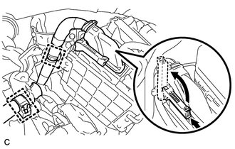
DISCONNECT WATER HOSE
-
REMOVE INVERTER WITH CONVERTER ASSEMBLY
-
SEPARATE INVERTER RESERVE TANK ASSEMBLY (for 2ZR-FXE)
-
SEPARATE INVERTER RESERVE TANK ASSEMBLY (for 5ZR-FXE)
-
REMOVE INVERTER TRAY BRACKET (for 2ZR-FXE)
-
REMOVE INVERTER TRAY BRACKET (for 5ZR-FXE)
-
DISCONNECT NO. 1 RADIATOR HOSE (for 2ZR-FXE)
-
DISCONNECT NO. 1 RADIATOR HOSE (for 5ZR-FXE)
-
DISCONNECT NO. 4 WATER BY-PASS HOSE (for 2ZR-FXE)
-
DISCONNECT NO. 4 WATER BY-PASS HOSE (for 5ZR-FXE)
-
REMOVE RADIATOR PIPE (for 2ZR-FXE)
-
REMOVE RADIATOR PIPE (for 5ZR-FXE)
-
DISCONNECT NO. 3 INVERTER COOLING HOSE (for 2ZR-FXE)
-
DISCONNECT NO. 3 INVERTER COOLING HOSE (for 5ZR-FXE)
-
DISCONNECT NO. 5 INVERTER COOLING HOSE (for 2ZR-FXE)
-
DISCONNECT NO. 5 INVERTER COOLING HOSE (for 5ZR-FXE)
-
DISCONNECT WIRE HARNESS
-
Disengage the 2 clamps.
-
Pull up the lever and disconnect the ECM connector.
-
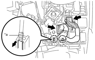
Text in Illustration *a Protective Tape Disconnect the 2 engine room junction block connectors.
-
Using a screwdriver, disengage the 2 claws.
Tech Tips
Tape the screwdriver tip before use.
-
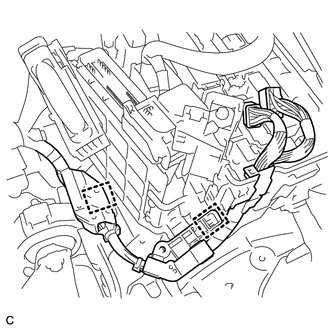
Disengage the 2 clamps.
-
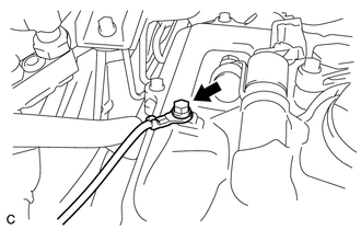
Remove the bolt and disconnect the earth wire from the engine assembly.
-
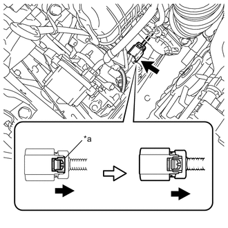
Text in Illustration *a Green-colored Lock Release the green-colored lock and disconnect the electric inverter compressor connector as shown in the illustration.
CAUTION:
Wear insulated gloves when performing the procedure.
Note
Insulate the electric inverter compressor connector by sealing it with tape.
-
Disconnect the resolver sensor connector.
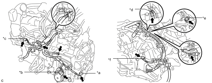
Text in Illustration *a Resolver Sensor Connector *b Shift Control Actuator Assembly Connector *c Throttle Body Assembly Connector *d Generator Cable Terminal Connector *e Engine Coolant Temperature Sensor Connector *f Motor Temperature Sensor Connector -
Disconnect the shift control actuator assembly connector.
-
Disconnect the throttle body assembly connector.
-
Disconnect the generator cable terminal connector.
-
Disconnect the engine coolant temperature sensor connector.
-
Disconnect the motor temperature sensor connector.
-
Remove the 3 bolts.
-
Disengage the 12 clamps.
-
-
SECURE STEERING WHEEL
-
REMOVE COLUMN HOLE COVER SILENCER SHEET
-
SEPARATE NO. 2 STEERING INTERMEDIATE SHAFT ASSEMBLY
-
SEPARATE NO. 1 STEERING COLUMN HOLE COVER SUB-ASSEMBLY
-
REMOVE FRONT NO. 3 ENGINE UNDER COVER (for 2ZR-FXE)
-
REMOVE FRONT NO. 3 ENGINE UNDER COVER (for 5ZR-FXE)
-
REMOVE FRONT CENTER FLOOR BRACE (for 2ZR-FXE)
-
REMOVE FRONT CENTER FLOOR BRACE (for 5ZR-FXE)
-
REMOVE FRONT EXHAUST PIPE ASSEMBLY (for 2ZR-FXE)
w/ Exhaust Heat Recirculation System Click here
w/o Exhaust Heat Recirculation System Click here
-
REMOVE FRONT EXHAUST PIPE ASSEMBLY (for 5ZR-FXE)
-
REMOVE FRONT AXLE SHAFT NUT LH
-
REMOVE FRONT AXLE SHAFT NUT RH
Tech Tips
Perform the same procedure as for the LH side.
-
SEPARATE FRONT SPEED SENSOR LH
-
SEPARATE FRONT SPEED SENSOR RH
Tech Tips
Perform the same procedure as for the LH side.
-
SEPARATE TIE ROD END SUB-ASSEMBLY LH
-
SEPARATE TIE ROD END SUB-ASSEMBLY RH
Tech Tips
Perform the same procedure as for the LH side.
-
SEPARATE FRONT STABILIZER LINK ASSEMBLY LH
-
SEPARATE FRONT STABILIZER LINK ASSEMBLY RH
Tech Tips
Perform the same procedure as for the LH side.
-
SEPARATE FRONT LOWER NO. 1 SUSPENSION ARM SUB-ASSEMBLY LH
-
SEPARATE FRONT LOWER NO. 1 SUSPENSION ARM SUB-ASSEMBLY RH
Tech Tips
Perform the same procedure as for the LH side.
-
SEPARATE FRONT DRIVE SHAFT ASSEMBLY LH
-
REMOVE FRONT DRIVE SHAFT ASSEMBLY LH
-
SEPARATE FRONT DRIVE SHAFT ASSEMBLY RH
Tech Tips
Perform the same procedure as for the LH side.
-
REMOVE FRONT DRIVE SHAFT ASSEMBLY RH
Tech Tips
Perform the same procedure as for the LH side.
-
REMOVE FRONT DRIVE SHAFT HOLE SNAP RING LH
-
REMOVE FRONT DRIVE SHAFT HOLE SNAP RING RH
Tech Tips
Perform the same procedure as for the LH side.
-
INSTALL ENGINE HANGERS
-
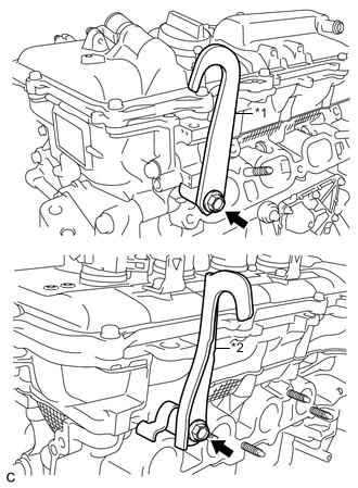
Text in Illustration *1 No. 1 Engine Hanger *2 No. 2 Engine Hanger Install the 2 engine hangers to the engine assembly with the 2 bolts.
- Torque:
- 43 N*m { 438 kgf*cm, 32 ft.*lbf }
Part Name Part No. No. 1 Engine Hanger 12281-37021 No. 2 Engine Hanger 12282-37011 Bolt 91552-81050 -
Attach a sling device to the engine hangers and a chain block.
-
-
REMOVE STARTER HOLE INSULATOR
-
Remove the 2 bolts and starter hole insulator from the engine assembly.
-
-
REMOVE FLYWHEEL HOUSING SIDE COVER
-
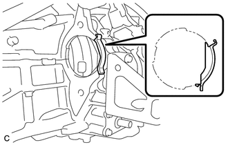
Remove the flywheel housing side cover from the engine assembly.
-
-
REMOVE FRONT ENGINE MOUNTING BRACKET LOWER REINFORCEMENT
-
REMOVE REAR SIDE RAIL REINFORCEMENT SUB-ASSEMBLY LH
-
REMOVE REAR SIDE RAIL REINFORCEMENT SUB-ASSEMBLY RH
Tech Tips
Perform the same procedure as for the LH side.
-
REMOVE FRONT SUSPENSION MEMBER REAR BRACE LH
-
REMOVE FRONT SUSPENSION MEMBER REAR BRACE RH
Tech Tips
Perform the same procedure as for the LH side.
-
REMOVE FRONT SUSPENSION CROSSMEMBER SUB-ASSEMBLY
-
REMOVE REAR ENGINE MOUNTING INSULATOR (for 2ZR-FXE)
-
REMOVE REAR ENGINE MOUNTING INSULATOR (for 5ZR-FXE)
-
SUPPORT HYBRID VEHICLE TRANSAXLE ASSEMBLY
-
Support the hybrid vehicle transaxle assembly with a transmission jack.
-
-
REMOVE FRONT CROSSMEMBER SUB-ASSEMBLY
-
Remove the bolt and nut from the front engine mounting insulator.
-
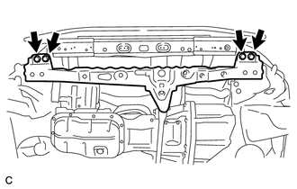
Remove the 4 bolts and front crossmember subassembly from the vehicle body.
-
-
REMOVE FRONT ENGINE MOUNTING INSULATOR (for 2ZR-FXE)
-
REMOVE FRONT ENGINE MOUNTING INSULATOR (for 5ZR-FXE)
-
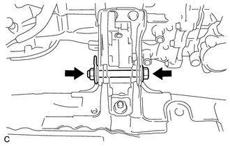
REMOVE ENGINE MOUNTING BRACKET LH
-
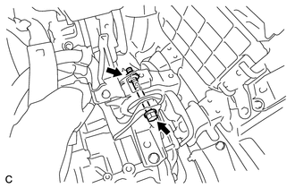
Remove the through bolt and nut, and separate the engine mounting insulator LH from the engine mounting bracket LH.
Note
Turn the nut while holding the bolt.
-
Remove the 3 bolts and engine mounting bracket LH from the hybrid vehicle transaxle assembly.
-
-
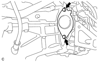
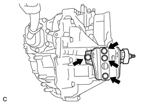
REMOVE HYBRID VEHICLE TRANSAXLE ASSEMBLY
-
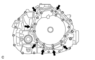
Remove the 7 bolts and hybrid vehicle transaxle assembly from the engine assembly.
Note
-
To avoid damage to the knock pins, do not pry between the hybrid vehicle transaxle assembly and engine assembly.
-
To prevent the splines of the damper from becoming misaligned, do not allow the hybrid vehicle transaxle assembly to hit the damper during hybrid vehicle transaxle assembly removal and installation.
-
-
-
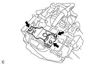
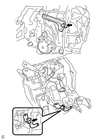
REMOVE FRONT ENGINE MOUNTING BRACKET
-
Remove the 3 bolts and front engine mounting bracket from the hybrid vehicle transaxle assembly.
-
-
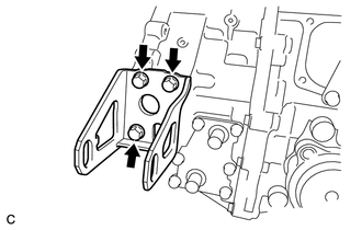
REMOVE REAR ENGINE MOUNTING BRACKET
-
Remove the 4 bolts and rear engine mounting bracket from the hybrid vehicle transaxle assembly.
-
-
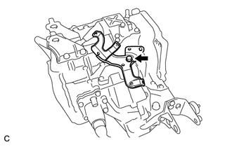
REMOVE WIRE HARNESS CLAMP BRACKET
-
Remove the 2 bolts and 2 wire harness clamp brackets from the hybrid vehicle transaxle assembly.
-
-
REMOVE MOTOR CABLE BRACKET
-
Remove the bolt and motor cable bracket from the hybrid vehicle transaxle assembly.
-
-
REMOVE GENERATOR CABLE
-
REMOVE MOTOR CABLE