DYNAMIC RADAR CRUISE CONTROL SYSTEM Cruise SET Indicator Light Circuit
DESCRIPTION
The power management control ECU illuminates the cruise SET indicator by sending indicator output demand signals to the combination meter assembly via CAN communication. The cruise SET indicator illuminates when the dynamic radar cruise control system is controlling vehicle speed. The cruise SET indicator light circuit uses CAN communication. If the cruise SET indicator is not functioning correctly, check for CAN communication DTCs before troubleshooting this circuit.
CAUTION / NOTICE / HINT
CAUTION:
Observe the following items for safety reasons when using the GTS:
-
Before using the GTS, read the instruction the GTS.
-
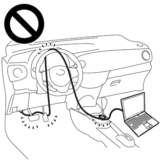
Prevent the GTS cable from being caught on the pedals, shift lever or steering wheel when driving with the GTS connected to the vehicle.
-
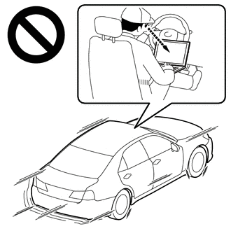
When driving the vehicle for testing purposes, 2 people are required. One person should operate the GTS while the other drives the vehicle.
PROCEDURE
-
PERFORM ACTIVE TEST USING GTS
-
Connect the GTS to the DLC3.
-
Turn the power switch on (IG).
-
Turn the GTS on.
-
Enter the following menus: Body Electrical / Combination Meter / Active Test.
-
Perform the Active Test according to the display on the GTS.
Combination Meter Tester Display Measurement Item Control Range Diagnostic Note Indicat. SET Cruise SET indicator light ON or OFF - Result Result Proceed to The cruise SET indicator in the combination meter assembly blinks or turns off according to the operation of the Active Test A The cruise SET indicator in the combination meter assembly does not blink or turn off according to the operation of the Active Test B
B 
GO TO METER / GAUGE SYSTEM Click here
A 
-
-
READ VALUE USING GTS
-
Turn the cruise control system on using the cruise control main switch (ON/OFF button).
-
Drive at a speed between approximately 40 km/h (25 mph) and 180 km/h (112 mph).
-
Enter the following menus: Powertrain / Radar Cruise 1 / Data List.
-
Read the Data List according to the display on the GTS.
Radar Cruise 1 Tester Display Measurement Item Range Normal Condition Diagnostic Note -SET Switch -SET switch status ON or OFF ON: -SET switch on
OFF: -SET switch off
- Result Result Proceed to The cruise SET indicator illuminates and turns off according to the operation of the cruise control main switch (-SET switch) A The cruise SET indicator does not illuminate but the Data List item -SET Switch changes according to the operation of the cruise control main switch (-SET switch) B The cruise SET indicator does not illuminate and the Data List item -SET Switch does not change according to the operation of the cruise control main switch (-SET switch) C
A
PROCEED TO NEXT SUSPECTED AREA SHOWN IN PROBLEM SYMPTOMS TABLE Click here
B
REPLACE COMBINATION METER ASSEMBLY Click here
C
REPLACE POWER MANAGEMENT CONTROL ECU Click here
-