EXHAUST PIPE GAS CONTROL ACTUATOR INSTALLATION
PROCEDURE
-
INSTALL EXHAUST PIPE GAS CONTROL ACTUATOR SUB-ASSEMBLY
-
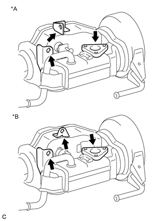
Text in Illustration *A w/ Pin Top Plate *B w/o Pin Top Plate Clean the installation surfaces and bolt holes of the exhaust pipe gas control actuator sub-assembly and front exhaust pipe assembly.
Note
Make sure no foreign matter enters the cooling system when the exhaust pipe gas control actuator sub-assembly is removed.
-
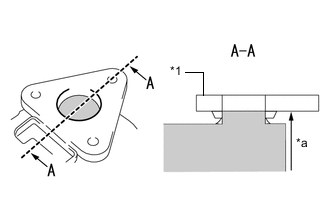
Text in Illustration *1 Flange *a Fill Up 
Coolant If the engine coolant spilled when removing the front exhaust pipe assembly, add engine coolant up to the bottom edge of the flange as shown in the illustration.
Tech Tips
If a large amount of air enters the cooling system, the load on the engine water pump assembly will increase.
-
w/o Pin Top Plate:
-
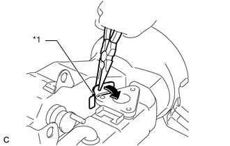
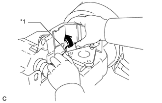
Text in Illustration *1 Small Insulator Using needle nose pliers, slightly tilt the small insulator in the direction shown by the arrow in the illustration to secure enough space to install the No. 2 exhaust pipe heat insulator.
Note
Depending on the date of vehicle production, some vehicles are not equipped with the small insulator.
-
-
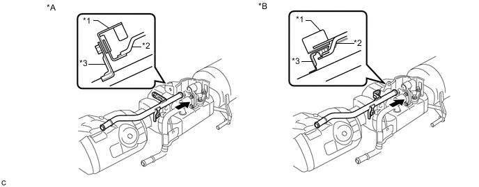
Text in Illustration *A w/ Pin Top Plate *B w/o Pin Top Plate *1 No. 2 Exhaust Pipe Heat Insulator *2 Front Exhaust Pipe Assembly Set the No. 2 exhaust pipe heat insulator on the front exhaust pipe assembly.
Note
Confirm that the No. 2 exhaust pipe heat insulator is installed in the correct position.
-
w/o Pin Top Plate:
-
Text in Illustration *1 Small Insulator Tilt the small insulator back toward the No. 2 exhaust pipe heat insulator.
Note
Depending on the date of vehicle production, some vehicles are not equipped with the small insulator.
-
-
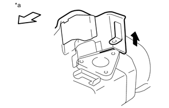
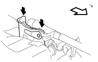
Text in Illustration *a Vehicle Front Lift the rear side of the No. 2 exhaust pipe heat insulator to allow the exhaust pipe gas control actuator sub-assembly to be installed below the flange on the No. 2 exhaust pipe heat insulator.
-
w/ Pin Top Plate:
-
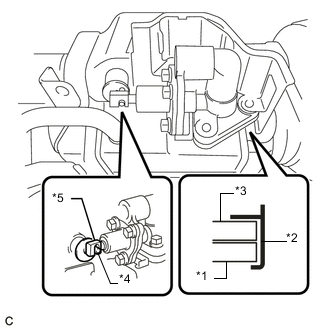
Text in Illustration *1 Front Exhaust Pipe Assembly *2 No. 2 Exhaust Pipe Heat Insulator *3 Exhaust Pipe Gas Control Actuator Sub-assembly *4 Pin Top Plate *5 Hook Loosely install the exhaust pipe gas control actuator sub-assembly, confirm the exhaust pipe gas control actuator sub-assembly is installed below the flange on the No. 2 exhaust pipe heat insulator and that the hook is engaged with the valve pin.
-
-
w/o Pin Top Plate:
-
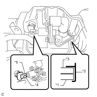
Text in Illustration *1 Front Exhaust Pipe Assembly *2 No. 2 Exhaust Pipe Heat Insulator *3 Exhaust Pipe Gas Control Actuator Sub-assembly *4 Valve Pin *5 Hook Loosely install the exhaust pipe gas control actuator sub-assembly, confirm the exhaust pipe gas control actuator sub-assembly is installed below the flange on the No. 2 exhaust pipe heat insulator and that the hook is engaged with the valve pin.
-
-
Loosely install the 3 bolts several threads.
-
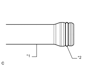
Text in Illustration *1 Exhaust By-pass Pipe *2 O-ring Apply clean coolant to the O-ring.
Note
Do not damage the O-ring or allow it to become contaminated with foreign matter during work.
-
Install the exhaust by-pass pipe to the exhaust pipe gas control actuator sub-assembly.
Text in Illustration *A w/o Exhaust Pipe Plate *B w/ Exhaust Pipe Plate *1 Front Exhaust Pipe Assembly *2 No. 2 Exhaust Pipe Heat Insulator *3 Exhaust By-pass Pipe - - Note
-
Make sure to insert the front exhaust pipe assembly into the exhaust pipe gas control actuator as far as possible.
-
Confirm that the front exhaust pipe assembly, exhaust by-pass pipe and No. 2 exhaust pipe heat insulator are positioned correctly.
-
When reusing the exhaust by-pass pipe, inspect the O-ring.
-
If the O-ring has scratches or cuts, replace the exhaust by-pass pipe.
-
Make sure that the O-ring and the fitting section of the exhaust pipe gas control actuator sub-assembly are free of oil or foreign matter.
-
Do not touch the O-ring or fitting section of the exhaust pipe gas control actuator sub-assembly.
-
-
w/ Pin Top Plate:
-
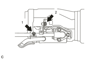
Install the 2 bolts in the order shown in the illustration.
- Torque:
- 8.5 N*m { 87 kgf*cm, 75 in.*lbf }
-
-
w/ Exhaust Pipe Plate:
-
Text in Illustration *a Vehicle Front Press in the No. 2 exhaust pipe heat insulator to align the installation holes of the exhaust by-pass pipe and No. 2 exhaust pipe heat insulator.
-
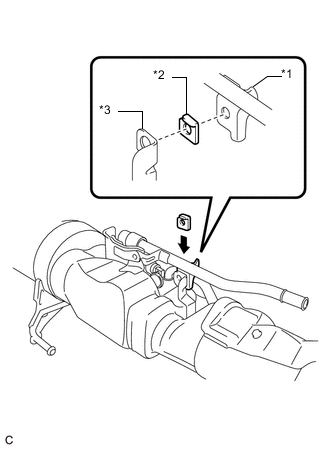
Text in Illustration *1 Exhaust By-pass Pipe *2 Exhaust Pipe Plate *3 Front Exhaust Pipe Assembly Insert the exhaust pipe plate between the exhaust by-pass pipe and front exhaust pipe assembly.
-
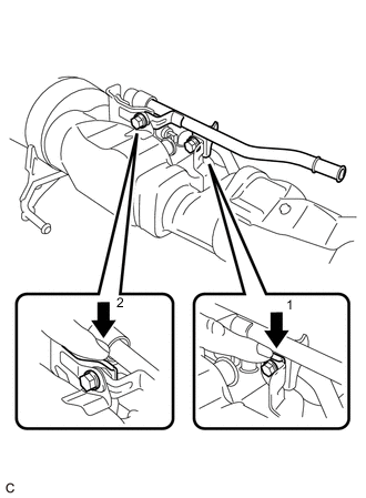
While holding down the No. 2 exhaust pipe heat insulator and exhaust pipe plate, fully tighten the 2 bolts in the order shown in the illustration.
- Torque:
- 8.5 N*m { 87 kgf*cm, 75 in.*lbf }
Note
If the procedure is not followed correctly, malfunctions or coolant leaks from the O-ring may occur.
-
-
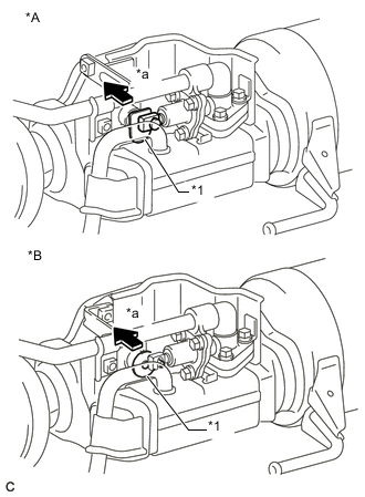
Text in Illustration *A w/ Pin Top Plate *B w/o Pin Top Plate *1 Valve Plate *a Insertion direction Confirm that the valve plate is positioned correctly by pressing the plate.
Tech Tips
If the valve plate is not positioned correctly, the final exhaust pipe gas control actuator sub-assembly position may be difficult to achieve.
-
w/ Pin Top Plate:
-
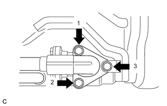
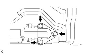
Tighten the 3 bolts in the order shown in the illustration in several steps.
- Torque:
- 5.0 N*m { 51 kgf*cm, 44 in.*lbf }
-
-
w/o Pin Top Plate:
-
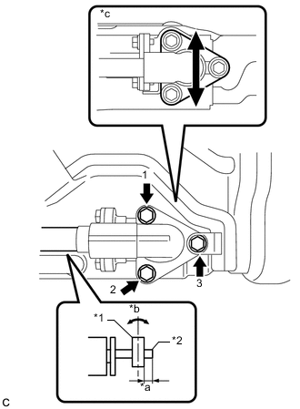
Text in Illustration *1 Hook *2 Valve Pin *a 3.5 to 6.5 mm (0.138 to 0.256 in.) *b Perpendicular *c Adjust the installation position Position the exhaust pipe gas control actuator subassembly so that 3.5 to 6.5 mm of the valve pin is protruding past the hook of the exhaust pipe gas control actuator sub-assembly.
-
Tighten the 3 bolts in the order shown in the illustration in several steps.
- Torque:
- 5.0 N*m { 51 kgf*cm, 44 in.*lbf }
-
Check that the hook of the exhaust pipe gas control actuator sub-assembly is at a point 3.5 to 6.5 mm from the end of the valve pin.
Tech Tips
-
If the hook is not installed within the specified range, loosen the 3 bolts of the exhaust pipe gas control actuator sub-assembly and 2 bolts of the exhaust by-pass pipe, then perform the steps from "Temporarily install the 3 bolts several threads".
-
If installation within the specified range cannot be obtained, replace the front exhaust pipe assembly.
-
-
-
Adjust the installation position of the exhaust by-pass pipe.
-
Loosen the 2 bolts slightly.
Note
Do not remove these 2 bolts.
-
Move the exhaust by-pass pipe up and down to properly settle the O-ring.
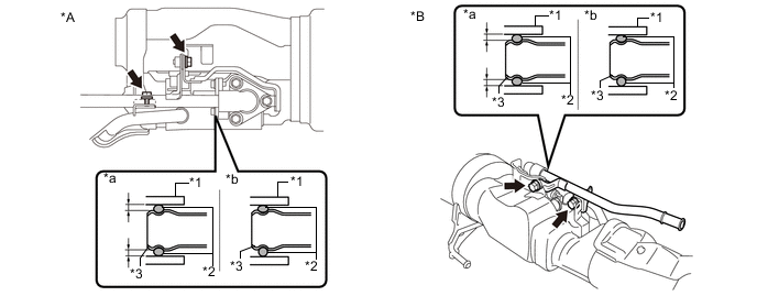
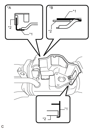
Text in Illustration *A w/ Pin Top Plate *B w/o Pin Top Plate *1 Exhaust Pipe Gas Control Actuator Sub-assembly *2 O-ring *3 Exhaust By-pass Pipe - - *a OK (O-ring is not deformed.) *b NG (O-ring is deformed.) Note
-
If this step is not performed, a coolant leak will develop.
-
Make sure to settle the O-ring to distribute the pressure applied to the upper part of the O-ring. Failure to do so may cause engine coolant to leak.
-
-
-
w/ Pin Top Plate:
-
Tighten the 2 bolts in the order shown in the illustration.
- Torque:
- 8.5 N*m { 87 kgf*cm, 75 in.*lbf }
-
-
w/o Pin Top Plate:
-
While holding down the No. 2 exhaust pipe heat insulator and exhaust pipe plate, fully tighten the 2 bolts in the order shown in the illustration.
- Torque:
- 8.5 N*m { 87 kgf*cm, 75 in.*lbf }
-
-
When replacing the exhaust pipe gas control actuator sub-assembly with a new one:
-
Remove the spacer from the new exhaust pipe gas control actuator sub-assembly.
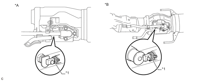
Text in Illustration *A w/ Pin Top Plate *B w/o Pin Top Plate *1 Spacer - - Note
To prevent a malfunction of the exhaust pipe gas control actuator sub-assembly, the spacer must be removed.
Tech Tips
The spacer is provided with a new exhaust pipe gas control actuator sub-assembly.
-
-
-
INSTALL FRONT EXHAUST PIPE ASSEMBLY
-
ADD COOLANT (for Engine)
-
INSPECT FOR COOLANT LEAK (for Engine)