EXHAUST MANIFOLD INSTALLATION
PROCEDURE
-
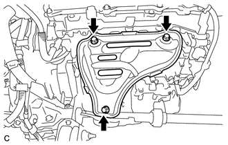
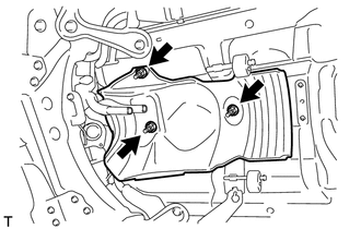
INSTALL NO. 2 EXHAUST MANIFOLD HEAT INSULATOR
-
Install the No. 2 exhaust manifold heat insulator with the 3 bolts.
- Torque:
- 12 N*m { 122 kgf*cm, 9 ft.*lbf }
-
-
INSTALL EXHAUST MANIFOLD
-
Install a new gasket.
-
Type A:
-
Install the exhaust manifold with the 5 nuts.
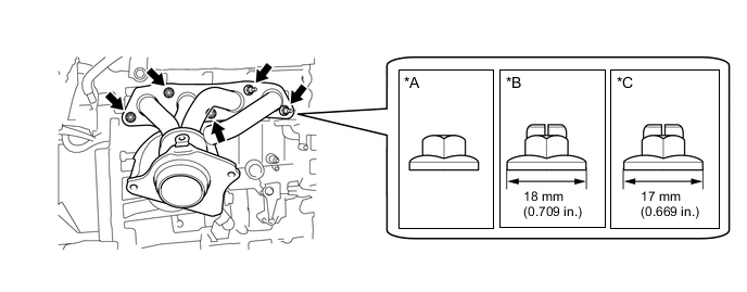
Text in Illustration *A Type A *B Type B *C Type C - - - Torque:
- 21 N*m { 214 kgf*cm, 15 ft.*lbf }
-
-
Type B and Type C:
-
Install the exhaust manifold with 5 new nuts.
- Torque:
- Type B
- 37 N*m { 377 kgf*cm, 27 ft.*lbf }
- Type C
- 26 N*m { 265 kgf*cm, 19 ft.*lbf }
-
-
-
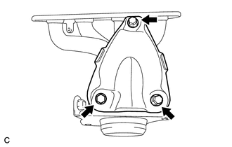
INSTALL MANIFOLD STAY
-
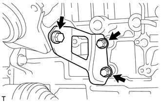
Install the manifold stay with the 3 bolts.
- Torque:
- 43 N*m { 438 kgf*cm, 32 ft.*lbf }
-
-
INSTALL AIR FUEL RATIO SENSOR
-
INSTALL NO. 1 EXHAUST MANIFOLD HEAT INSULATOR
-
Install the No. 1 exhaust manifold heat insulator with the 3 bolts.
- Torque:
- 12 N*m { 122 kgf*cm, 9 ft.*lbf }
-
-
INSTALL FRONT NO. 1 FLOOR HEAT INSULATOR
-
Install the front No. 1 floor heat insulator with the 3 nuts.
- Torque:
- 5.5 N*m { 56 kgf*cm, 49 in.*lbf }
-
-
INSTALL FRONT EXHAUST PIPE ASSEMBLY
-
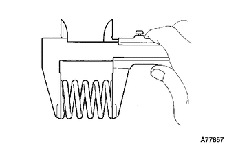
Using a vernier caliper, measure the free length of the compression springs.
Minimum (front) 41.5 mm (1.63 in.) Minimum (rear) 38.5 mm (1.52 in.) Tech Tips
If the free length is less than minimum, replace the compression spring.
-
Temporarily install 2 new gaskets to the exhaust manifold and front exhaust pipe assembly.
-
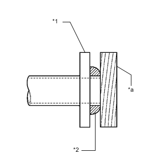
Text in Illustration *1 Exhaust Manifold or Front Exhaust Pipe Assembly (TWC: Front and Rear Catalyst) *2 Gasket *a Wooden Block Using a plastic hammer and wooden block, tap in each gasket until its surface is flush with the exhaust manifold and front exhaust pipe assembly (TWC: Front and Rear Catalyst).
Note
-
Be careful with the installation direction of the gaskets.
-
Do not reuse the gaskets.
-
Do not damage the gaskets.
-
Do not push in the gasket by using the exhaust pipe when connecting it.
-
-
Connect the front exhaust pipe assembly (TWC: Front and Rear Catalyst) to the 2 exhaust pipe supports.
-
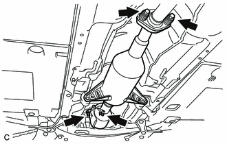
Install the front exhaust pipe assembly (TWC: Front and Rear Catalyst) with the 4 bolts and 4 compression springs.
- Torque:
- 43 N*m { 438 kgf*cm, 32 ft.*lbf }
-
Connect the 3 clamps and heated oxygen sensor connector.
-
-
INSTALL FRONT CENTER FLOOR BRACE
-
INSTALL FRONT NO. 3 ENGINE UNDER COVER
-
INSTALL NO. 1 ENGINE UNDER COVER
-
INSTALL NO. 2 CYLINDER HEAD COVER
-
INSTALL OUTER COWL TOP PANEL SUB-ASSEMBLY
-
INSTALL COWL BODY MOUNTING REINFORCEMENT LH
-
INSTALL NO. 2 HEATER AIR DUCT SPLASH SHIELD SEAL
-
INSTALL NO. 1 HEATER AIR DUCT SPLASH SHIELD SEAL
-
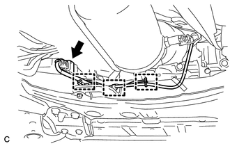
INSTALL WINDSHIELD WIPER MOTOR AND LINK ASSEMBLY
-
INSPECT FOR EXHAUST GAS LEAK