FUEL INJECTOR INSPECTION

PROCEDURE
-
INSPECT FUEL INJECTOR ASSEMBLY
-
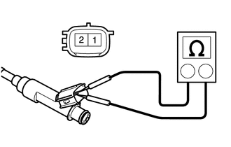
Check the resistance.
-
Using an ohmmeter, measure the resistance according to the value(s) in the table below.
Standard Resistance Tester Connection Condition Specified Condition 1 - 2 20°C (68°F) 11.6 to 12.4 Ω If the result is not as specified, replace the injector assembly.
-
-
Check the operation.
Inspect the injector injection volume.
CAUTION:
Perform the inspection in a well-ventilated area.
Do not perform the inspection near a open flame.
-
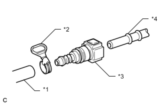
Text in Illustration *1 SST
(Hose)
*2 SST
(Hose Band)
*3 SST
(Fuel Tube Connector)
*4 Fuel Pipe (Vehicle Side) Connect SST (fuel tube connector) to SST (hose) with SST (hose band), and then connect them to the fuel pipe (vehicle side).
- SST
- 09268-31014 ( 09268-41500, 09268-41700, 95336-08070 )
Note
Ensure that the SST connector O-rings are not damaged and are free of foreign matter as they are used to seal the connections between the fuel tube connector and fuel pipe.
-
Install a new O-ring onto the fuel injector assembly.
-
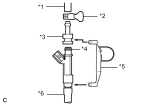
Text in Illustration *1 SST
(Hose)
*2 SST
(Hose Band)
*3 SST
(Adapter)
*4 O-ring *5 SST
(Clamp)
*6 Vinyl Tube Connect SST (adapter and hose) to the injector assembly, and hold the injector assembly and union with SST (clamp).
- SST
- 09268-31014 ( 09268-41110, 09268-41300, 09268-41700, 95336-08070 )
-
Install a vinyl tube onto the injector.
CAUTION:
Install a suitable vinyl tube onto the injector assembly to prevent gasoline from spraying.
-
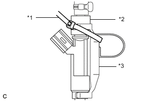
Text in Illustration *1 SST
(Tie Band)
*2 SST
(Adapter)
*3 SST
(Clamp)
Tie the clamp and adapter together with a tie band as shown in the illustration.
- SST
- 09268-31014 ( 09268-41110, 09268-41300, 09268-41800 )
-
Set the injector assembly in a graduated cylinder.
-
Operate the fuel pump Click here.
-
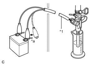
Text in Illustration *1 SST
(Wire)
*a Connect Connect SST (wire) to the injector assembly and the auxiliary battery for 15 seconds, and measure the injection volume with the graduated cylinder. Test each injector 2 or 3 times.
- SST
- 09842-30080
Note
Always switch the voltage on and off at the auxiliary battery side, not the injector side.
Standard Injection Volume Tester Connection Condition Specified Condition Positive terminal - Ground terminal Per 15 seconds 60 to 73 cc (3.7 to 4.5 cu.in.) Difference between each injector 13 cc (0.8 cu.in.) or less If the injection volume is not as specified, replace the injector assembly.
-
-
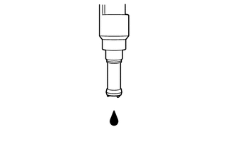
Inspect for leaks.
-
In the condition above, disconnect the test probes of SST (wire) from the auxiliary battery and check the fuel leaks from the injector.
Standard fuel drop 1 drop or less every 12 minutes If there are excessive leaks, replace the injector assembly.
-
-