FUEL PUMP REMOVAL

PROCEDURE
-
PRECAUTION
Note
After turning the power switch off, waiting time may be required before disconnecting the cable from the negative (-) auxiliary battery terminal. Therefore, make sure to read the disconnecting the cable from the negative (-) auxiliary battery terminal notice before proceeding with work Click here.
-
DISCHARGE FUEL SYSTEM PRESSURE
-
REMOVE REAR NO. 2 FLOOR BOARD
-
REMOVE REAR DECK FLOOR BOX
-
REMOVE REAR NO. 3 FLOOR BOARD
-
REMOVE DECK FLOOR BOX RH
-
REMOVE REAR FLOOR BOARD UPPER NO. 3 PLATE
-
DISCONNECT CABLE FROM NEGATIVE AUXILIARY BATTERY TERMINAL
Note
When disconnecting the cable, some systems need to be initialized after the cable is reconnected Click here.
-
REMOVE REAR SEAT CUSHION ASSEMBLY
-
REMOVE REAR SEAT CUSHION LOCK HOOK
-
REMOVE REAR FLOOR SERVICE HOLE COVER
-
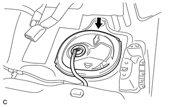
Remove the rear floor service hole cover.
-
Disconnect the connector from the fuel suction tube assembly.
-
-
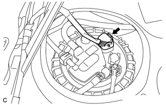
DISCONNECT FUEL TANK MAIN TUBE SUB-ASSEMBLY
-
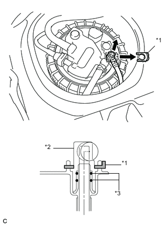
Text in Illustration *1 Tube Joint Clip *2 Fuel Tube Joint *3 O-ring Remove the tube joint clip, then pull the fuel tube joint out of the plug of the fuel suction tube assembly.
Note
-
Check that there is no dirt or other foreign matter around the fuel tube joint before disconnecting it. Clean the joint if necessary.
-
It is necessary to prevent dirt or foreign matter from entering the joint. If dirt or foreign matter gets in the joint, the O-rings may not seal properly.
-
Only disconnect the joint by hand.
-
Do not bend, kink or twist the nylon tubes.
-
Protect the contact surfaces by covering it with a plastic bag.
-
-
-
DISCONNECT NO. 1 FUEL EVAPORATION TUBE SUB-ASSEMBLY
-
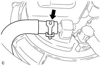
Loosen the clip and disconnect the No. 1 fuel evaporation tube sub-assembly from the fuel suction tube assembly.
-
-
DISCONNECT NO. 1 CHARCOAL CANISTER OUTLET HOSE
-
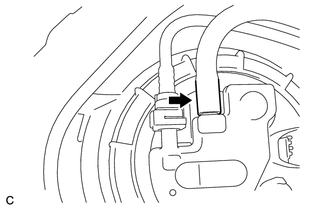
Disconnect the No. 1 charcoal canister outlet hose from the fuel suction tube assembly.
-
-
DISCONNECT FUEL TANK EVAPORATION TUBE
-
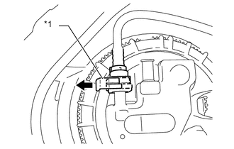
Text in Illustration *1 Retainer Release the retainer and disconnect the fuel tank evaporation tube from the fuel suction tube assembly.
-
-
REMOVE FUEL PUMP GAUGE RETAINER
-
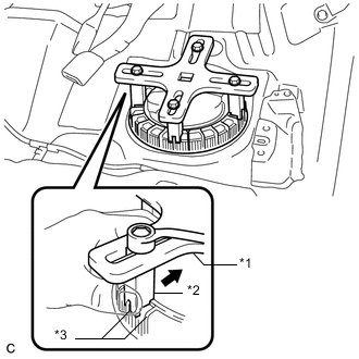
Text in Illustration *1 SST
(Plate)
*2 SST
(Claw)
*3 Rib Temporarily install the SST plate and claws to the fuel pump gauge retainer.
- SST
- 09808-14030 ( 09808-01030, 09808-01040, 09808-01050 )
Tech Tips
Engage the SST claws securely with the fuel pump gauge retainer ribs to secure SST.
-
While pressing the claws of SST to the fuel pump gauge retainer ribs securely, tighten the bolts.
Tech Tips
Install SST while pressing the SST claws toward the fuel pump gauge retainer (towards the center of SST).
-
Install the SST handle.
-
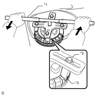
Text in Illustration *1 SST
(Handle)
*2 SST
(Plate)
*3 SST
(Claw)
Lightly press down on SST to prevent it from separating from the retainer. While pressing SST, rotate the handle slowly to loosen the retainer.
- SST
- 09808-14030 ( 09808-01010, 09808-01020, 09808-01030, 09808-01040, 09808-01050 )
Note
-
Do not use any tools other than specified in this operation. Damage to the fuel pump gauge retainer or the fuel tank may result.
-
Do not press down on SST excessively as this may make the retainer hard to rotate, and may damage components.
-
Make sure to rotate the SST handle horizontally. If the SST handle is rotated at an angle, SST may come off.
-
Do not spin SST too fast or use an impact wrench as this may result in damage to components.
-
If SST comes off of the retainer, loosen the SST bolts and reinstall SST.
Tech Tips
The ribs on the fuel pump gauge retainer can be fitted into the tips of SST.
-
Remove the fuel pump gauge retainer while holding the fuel suction tube assembly by hand.
-
-
REMOVE FUEL SUCTION TUBE ASSEMBLY WITH PUMP AND GAUGE
-
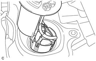
Remove the fuel suction tube assembly with pump and gauge from the fuel tank.
Note
Make sure that the fuel sender gauge arm does not bend.
-
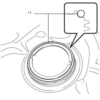
Text in Illustration *1 Gasket Remove the gasket from the fuel tank.
-