ACCELERATOR PEDAL SENSOR ON-VEHICLE INSPECTION
PROCEDURE
-
INSPECT ACCELERATOR PEDAL SENSOR ASSEMBLY
-
Connect the intelligent tester to the DLC3.
-
Turn the power switch on (IG).
-
Turn the intelligent tester on.
-
Enter the following menus: Powertrain / Hybrid Control / Data List / Accel Pedal Pos #1, Accel Pedal Pos #2.
-
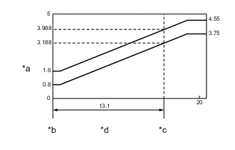
Text in Illustration *a Accelerator Pedal Position Sensor Output Voltage (V) *b Accelerator Pedal Fully Released *c Accelerator Pedal Fully Depressed *d Accelerator Pedal Turning Angle (°) Read the Data List.
Result Tester Display Accelerator Pedal Condition Specified Condition Accel Pedal Pos #1 Not depressed (8 to 28%) 0.4 to 1.4 V Fully depressed (62 to 92%) 3.1 to 4.6 V Not depressed → Fully depressed → Not depressed (Accelerator pedal should be operated slowly) Value changes progressively as shown in the illustration Accel Pedal Pos #2 Not depressed (20 to 44%) 1.0 to 2.2 V Fully depressed (78 to 100%) 3.9 to 5.0 V Not depressed → Fully depressed → Not depressed (Accelerator pedal should be operated slowly) Value changes progressively as shown in the illustration If the result is not as specified, check the accelerator pedal sensor assembly, wire harness or ECM.
-