POWER MODULE INTELLIGENT TRANSISTOR REASSEMBLY

CAUTION / NOTICE / HINT
Note
Do not cross-thread the bolts when installing them.
Tech Tips
Prepare 2 tubes of thermal grease X-23-7884-4 when replacing the power module intelligent transistor kit.
-
for Europe : 08887-83080
-
except Europe : 08887-02809
PROCEDURE
-
REMOVE THERMAL GREASE
-
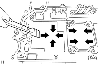
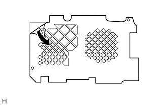
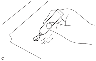
Using a scraper with its tip wrapped with protective tape, remove any remaining thermal grease from the hybrid vehicle converter kit as shown in the illustration.
Note
-
To prevent thermal grease from entering the hybrid vehicle converter kit, remove it by moving the scraper from the sides toward the center as shown in the illustration.
-
Keep the parts free from foreign matter.
-
Keep thermal grease away from other parts.
-
Do not spray non-residue solvent directly onto the parts when cleaning.
-
Clean parts with a piece of cloth saturated with non-residue solvent.
-
Do not use compressed air when cleaning to prevent dust from flying.
-
-
Using a piece of cloth, remove the thermal grease.
Tech Tips
It is acceptable to leave a small amount of thermal grease in the grooves.
-
-
REMOVE SEAL PACKING (FROM HYBRID CONVERTER KIT CONTACT SURFACE)
Note
-
Only remove seal packing which is uneven, has peeled off or seeped out from between the contact surfaces.
-
Do not drop any removed seal packing into the hybrid vehicle converter kit.
-
Do not bend the bus-bars.
-
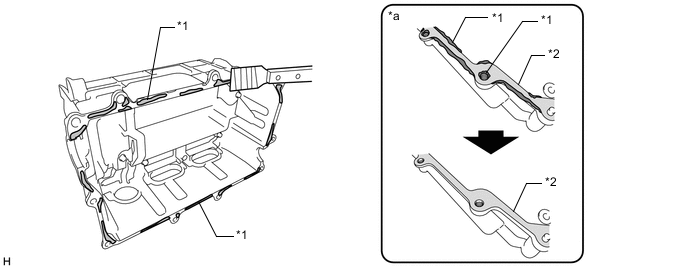
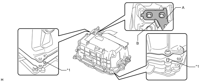
Install the 2 stud bolts and set the hybrid vehicle converter kit on its side as shown in the illustration.
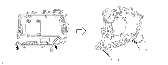
Text in Illustration *1 Stud Bolt - - Note
To prevent the hybrid vehicle converter kit from falling over, hold it with a hand or place an object behind it.
-
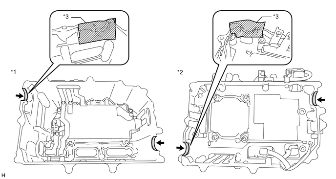
Using a finger or a scraper with its tip wrapped with protective tape, remove any remaining seal packing which is uneven, has peeled off or seeped out from around the contact surface shown in the illustration and inside the bolt holes.
Note
Do not bend the bus-bars.
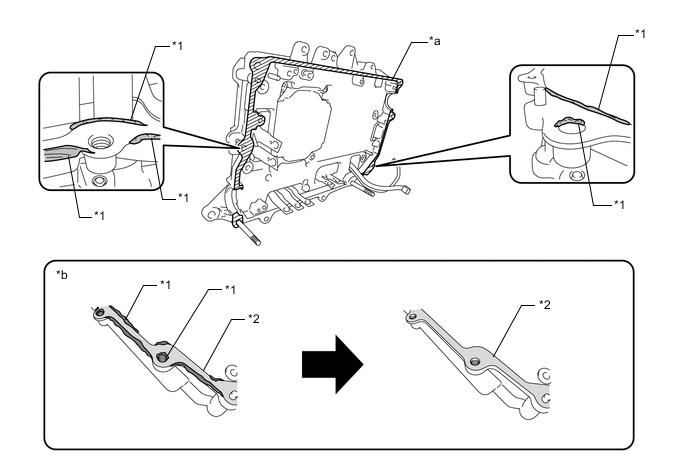
Text in Illustration *1 Seeped Out or Uneven Seal Packing *2 Light Coat of Seal Packing Remaining on Contact Surface *a Contact Surface *b Minimum Requirement for Removal of Seal Packing -
While supporting the hybrid vehicle converter kit by hand, using a finger or a scraper with its tip wrapped with protective tape, remove any remaining seal packing which is uneven, has peeled off or seeped out from around the contact surface shown in the illustration and inside the bolt holes.
Text in Illustration *a Contact Surface - - -
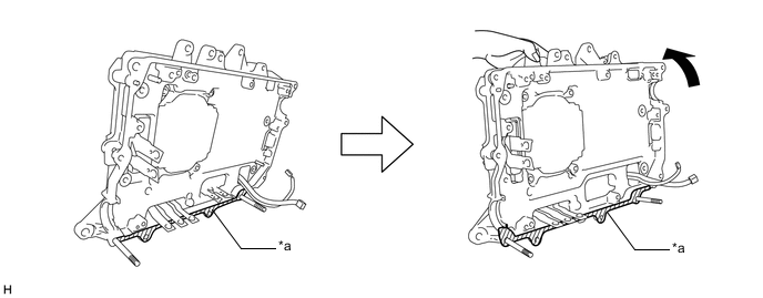
Remove the 2 stud bolts.
-
-
REMOVE SEAL PACKING (FROM INVERTER CASE WITH CONDENSER CONTACT SURFACE)
Note
-
Only remove seal packing which is uneven, has peeled off or seeped out from between the contact surfaces.
-
Do not drop any removed seal packing into the inverter case with condenser.
-
Do not bend the bus-bars.
-
Set the inverter case with condenser on its side as shown in the illustration.
Note
To prevent the inverter case with condenser from falling over, hold it by hand or place an object behind it.
-
Using a finger or a scraper with its tip wrapped with protective tape, remove any remaining seal packing which is uneven, has peeled off or seeped out from around the contact surface shown in the illustration and inside the bolt holes.
Text in Illustration *1 Seeped Out or Uneven Seal Packing *2 Light Coat of Seal Packing Remaining on Contact Surface *a Minimum Requirement for Removal of Seal Packing - -
-
-
REMOVE ADHESIVE (FROM NO. 1 AND NO. 2 INVERTER DRAIN PLUGS SEALING SURFACE)
-
Text in Illustration *1 Protective Tape Remove the protective tape from the installation holes of the No. 1 and No. 2 inverter drain plugs.
-
Text in Illustration *1 Protective Tape Apply protective tape to the No. 1 and No. 2 inverter drain plugs installation holes from the inside.
Note
Do not bend the bus-bars when applying protective tape.
-
Text in Illustration *1 Sealing Surface Using a scraper with its tip wrapped with protective tape, remove any remaining adhesive from the sealing surface of 2 inverter drain plugs.
Note
Do not damage the sealing surfaces.
-
Remove any adhesive shavings particles using tape or equivalent.
-
Remove the protective tape from the inside of the inverter case with condenser.
-
Text in Illustration *1 Protective Tape Apply protective tape to the installation holes of the No. 1 and No. 2 inverter drain plugs as shown in the illustration.
-
-
REMOVE RESIDUE (FROM INVERTER SIGNAL CONNECTOR COVER SEALING SURFACE)
-
Text in Illustration *1 Protective Tape Apply protective tape to the area shown in the illustration to prevent removed residue from entering the inverter case with condenser.
-
Using 600-grit sandpaper, remove the residue from each grommet sealing surface until it feels smooth.
Note
-
Use 600-grit or higher sandpaper.
-
Do not allow removed residue to enter the inverter case with condenser or hybrid vehicle converter kit.
-
Do not touch or allow grease or oil to contact the sealing surfaces of the inverter case with condenser.
-
-
Remove any adhesive particles using tape or equivalent.
-
Remove the protective tape.
-
Thoroughly wash hands after performing this step.
Tech Tips
This step is not necessary if performing the "Remove Residue (from Grommet Sealing Surface)" procedure next.
-
-
REMOVE RESIDUE (FROM GROMMET SEALING SURFACE)
Tech Tips
Perform the following procedure only when there is residue on the grommet sealing surfaces:
-
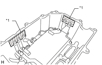
Apply protective tape to the areas shown in the illustration to prevent removed residue from entering the inverter case with condenser and hybrid vehicle converter kit.
Text in Illustration *1 Inverter Case with Condenser *2 Hybrid Vehicle Converter Kit *3 Protective Tape - - -
Using 600-grit sandpaper, remove the residue from each grommet sealing surface until it feels smooth.
Text in Illustration *a Residue - - Note
-
Use 600-grit or higher sandpaper.
-
Do not allow removed residue to enter the inverter case with condenser or hybrid vehicle converter kit.
-
-
Remove any adhesive shavings particles using tape or equivalent.
-
Remove the protective tape.
-
Thoroughly wash hands after performing this step.
-
-
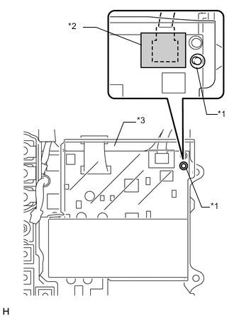
CLEAN INVERTER SIGNAL CONNECTOR COVER
-
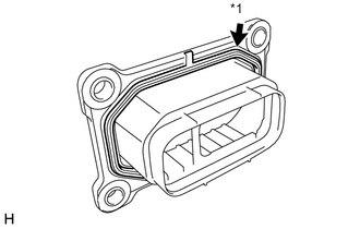
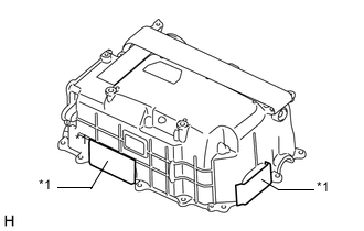
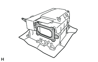
Text in Illustration *1 Gasket Remove the gasket from the inverter signal connector cover. Wash the gasket and inverter signal connector cover with water and dry them completely.
Note
Do not damage the gasket.
-
Thoroughly wash hands after performing this step.
-
-
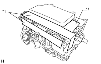
INSTALL POWER MODULE INTELLIGENT TRANSISTOR KIT
Note
-
Do not touch the circuit board.
-
Do not allow any moisture to come into contact with the circuit board.
-
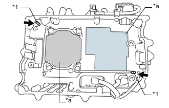
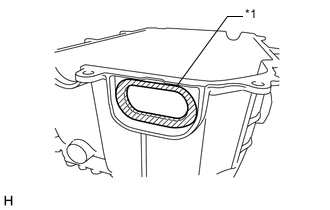
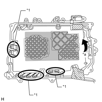
Text in Illustration *1 Guide Pins *a Thermal Grease Contacting Area Place the hybrid vehicle converter kit so that the guide pins are positioned as shown in the illustration and clean the thermal grease contacting area of the hybrid vehicle converter kit.
Tech Tips
Clean the hybrid vehicle converter kit contact surfaces with a piece of cloth saturated with non-residue solvent.
-
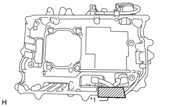
Text in Illustration *1 Protective Tape Apply protective tape to the wire harness to keep it free from grease.
-
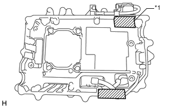
Text in Illustration *1 Protective Tape Apply protective tape to prevent grease from entering the hybrid vehicle converter kit.
-
Remove the protective paper from the masking seal.
-
Align the guide holes of the masking seal with the guide pins as shown in the illustration, and attach the masking seal to the hybrid vehicle converter kit.
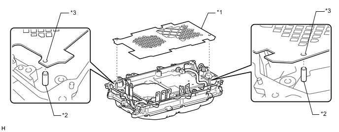
Text in Illustration *1 Masking Seal *2 Guide Pins *3 Guide Hole - - -
Check that the masking seal is attached correctly, then firmly press on it with your fingers to securely attach it.
Note
-
Securely attach the masking seal without leaving any air bubbles.
-
Do not touch the bus-bars when attaching the masking seal.
-
-
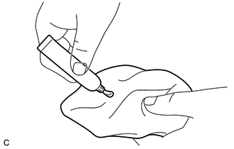
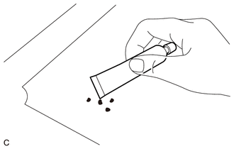
Gently squeeze the tube of thermal grease and apply a small amount to a piece of cloth.
Tech Tips
Some clear liquid may come out first. Squeeze it out completely onto a piece of cloth.
-
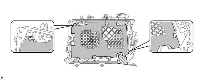
Apply thermal grease to 13 places as shown in the illustration.
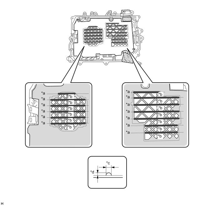
Text in Illustration *a Reference Line *b Almost equally spaced *c Approximately 6.0 mm (0.236 in.) *d Approximately 2.0 mm (0.0787 in.) -
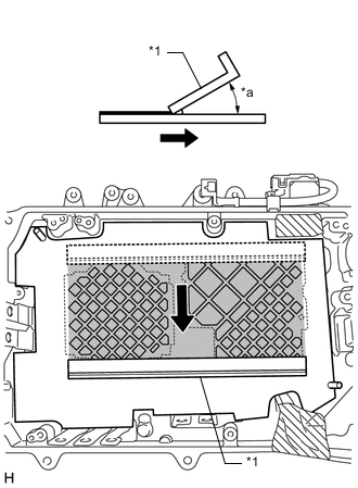
Text in Illustration *1 SST *a 45° Using SST, carefully apply the thermal grease smoothly and evenly by spreading it as shown in the illustration. (Procedure A)
- SST
- 09891-47010
Note
-
Before performing work, check that the thermal grease contacting area of SST is not damaged.
-
Apply the thermal grease smoothly and evenly to ensure proper heat transfer.
-
Keep SST at a 45-degree angle and perform work carefully.
-
Change the orientation of SST as shown in the illustration. (Procedure B)
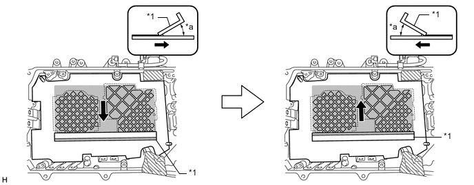
Text in Illustration *1 SST - - *a 45° - - -
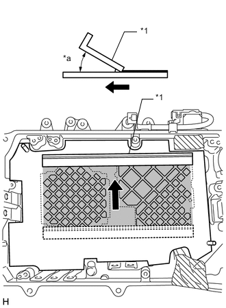
Text in Illustration *1 SST *a 45° Using SST, carefully apply the thermal grease smoothly and evenly by spreading it as shown in the illustration. (Procedure C)
-
Repeat steps A through C until the thermal grease is smooth and even.
-
Check that the thermal grease has been applied smoothly and evenly.
-
If the thermal grease layer is uneven and the part surface shows through, apply more thermal grease.
-
Using SST, carefully apply the thermal grease smoothly and evenly.
Note
-
Apply the thermal grease smoothly and evenly to ensure proper heat transfer.
-
Keep SST at a 45-degree angle and perform work carefully.
-
-
If foreign matter has attached to the part surface, scrape it off using the edge of the thermal grease tube, and apply more thermal grease.
-
Using SST, carefully apply the thermal grease smoothly and evenly.
Note
-
Apply the thermal grease smoothly and evenly to ensure proper heat transfer.
-
Keep SST at a 45-degree angle and perform work carefully.
-
-
Check that the thermal grease has been applied smoothly and evenly.
-
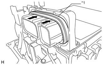
Text in Illustration *1 Bus-bar *a Remove Remove the masking seal from the hybrid vehicle converter kit.
Note
-
Slowly remove the masking seal without touching the thermal grease surface.
-
Be careful not to touch the bus-bars when removing the masking seal.
-
-
Remove the protective tape.
-
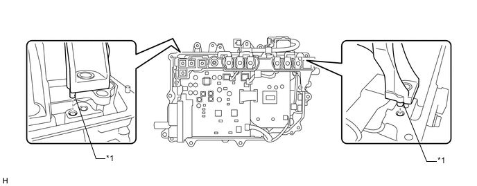
Align the guide holes with the guide pins as shown in the illustration, and temporarily install the power module intelligent transistor kit to the hybrid vehicle converter kit.
Text in Illustration *1 Guide Pins *2 Guide Hole (Oblong Hole) *3 Guide Hole (Circular Hole) - - Note
-
Do not apply any force the coolant pipes.
-
Make sure to align the guide pins correctly.
-
Be careful not to deform the bus-bars.
-
-
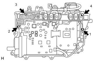
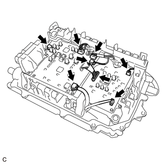
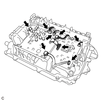
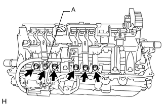
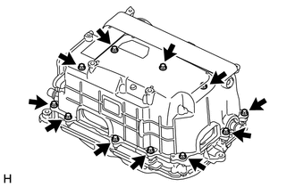
Install the power module intelligent transistor kit with the 4 bolts.
-
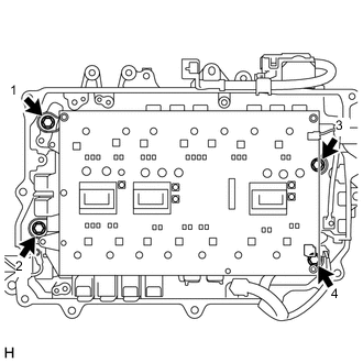
Temporarily tighten the 4 bolts evenly in several steps in the order shown in the illustration, then fully tighten them.
- Torque:
- 6.0 N*m { 61 kgf*cm, 53 in.*lbf }
-
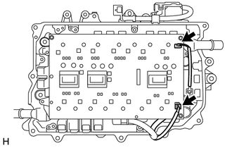
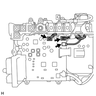
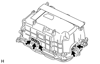
Connect the 2 connectors to the power module intelligent transistor kit.
-
Install the 5 bolts to the bus-bars.
- Torque:
- 6.0 N*m { 61 kgf*cm, 53 in.*lbf }
Note
Do not touch the bus-bars.
-
-
INSTALL MG CONTROL COMPUTER WITH BRACKET SUB-ASSEMBLY
Note
-
Do not touch the circuit board.
-
Do not allow any moisture to come into contact with the circuit board.
-
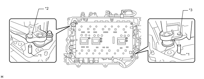
Align the holes of the MG control computer with bracket sub-assembly with the guide pins and temporarily install the power module intelligent transistor kit to the hybrid converter kit.
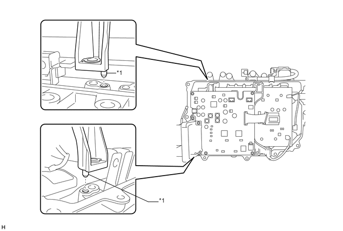
Text in Illustration *1 Guide Pins - - Note
Make sure to align the guide pins correctly.
-
Install the MG control computer with bracket sub-assembly with the 4 bolts.
-
Using an 8 mm deep socket wrench, temporarily tighten the 4 bolts evenly in several steps in the order shown in the illustration, then fully tighten them.
- Torque:
- 4.5 N*m { 46 kgf*cm, 40 in.*lbf }
-
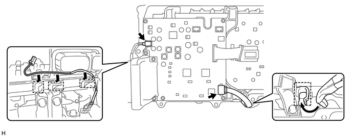
Engage the 2 wire harnesses to the 4 clamps.
-
Connect the 2 connectors to the MG control computer with bracket sub-assembly.
-
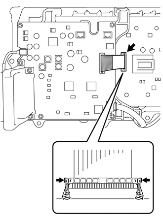
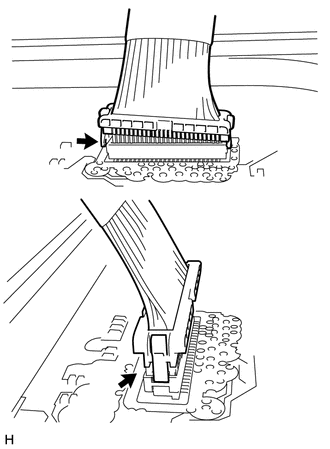
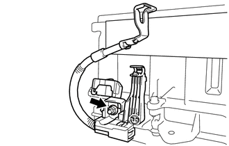
Disengage the lock claws of the white resin connector and connect the flat cable to the power module intelligent transistor kit.
-
Check that the flat cable is connected securely.
Note
If the flat cable is not fully connected, connect it securely.
-
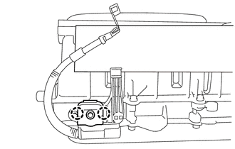
Text in Illustration *1 Gasket If the gasket of the inverter signal connector is protruding, fully push it in.
-
-
INSTALL INVERTER TERMINAL WITH SENSOR SUB-ASSEMBLY
Note
-
Do not touch the circuit board.
-
Do not allow any moisture to come into contact with the circuit board.
-
For inverter with converter assembly with part number G9200-76010 or G9200-76011: Make sure to replace the inverter current sensor sub-assembly and inverter wire sub-assembly at the same time when replacing the MG control computer with bracket sub-assembly Click here.
-
Align the holes of the power module intelligent transistor kit with the guide pins and temporarily install the power module intelligent transistor kit to the hybrid vehicle converter kit.
Text in Illustration *1 Guide Pins - - Note
Make sure to align the guide pins correctly.
-
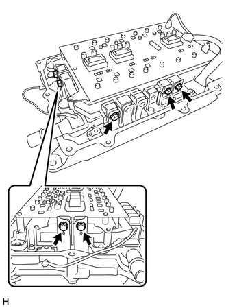
Install the inverter terminal with sensor sub-assembly with the 4 bolts.
-
Temporarily tighten the 4 bolts evenly in several steps in the order shown in the illustration, then fully tighten them.
- Torque:
- 4.5 N*m { 46 kgf*cm, 40 in.*lbf }
-
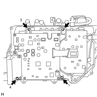
Connect the 3 connectors to the MG control computer with bracket sub-assembly.
Note
The location of the connectors varies depending on the part number of the inverter with converter assembly. Confirm the part number before performing work.
-
For inverter with converter assembly with part number G9200-76010 or G9200-76011:
-
For inverter with converter assembly with part number other than G9200-76010 or G9200-76011:
-
-
Check that the 7 connectors and flat cable are connected securely as shown in the illustration.
-
For inverter with converter assembly with part number G9200-76010 or G9200-76011:
-
For inverter with converter assembly with part number other than G9200-76010 or G9200-76011:
-
-
If a pen sheet is provided, check the installation condition of the pen sheet.
Note
-
Do not touch the circuit board.
-
Do not allow any moisture to come into contact with the circuit board.
-
While ensuring that the pen sheet does not interfere with components of the circuit board, insert the pen sheet between the inverter terminal with sensor sub-assembly and MG control computer with bracket sub-assembly.
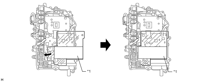
Text in Illustration *1 PEN Sheet - - -
Text in Illustration *1 Guide Pin *2 Double-sided Tape *3 PEN Sheet Set the pen sheet so that the pin of the motor generator control computer sub-assembly is aligned with the guide hole as shown in the illustration.
-
Attach the double-sided tape of the pen sheet to the connector shown in the illustration.
-
-
Install the 6 bolts to the bus-bars.
- Torque:
- 6.0 N*m { 61 kgf*cm, 53 in.*lbf }
Note
Do not touch the bus-bars.
-
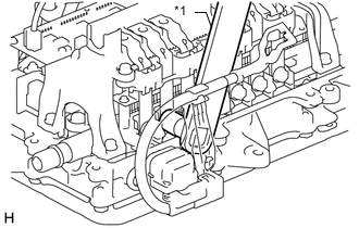
Text in Illustration *1 SST If the No. 2 engine room wire is installed, install the bolt (A) using SST as shown in the illustration.
- SST
- 09961-00950
- Torque:
- without SST
- 6.0 N*m { 61 kgf*cm, 53 in.*lbf }
- with SST
- 3.3 N*m { 34 kgf*cm, 29 in.*lbf }
Note
This torque value is effective when SST is parallel to the torque wrench.
-
-
INSTALL INVERTER CASE WITH CONDENSER
Note
-
Do not touch the circuit board.
-
Do not allow any moisture to come into contact with the circuit board.
-
Do not touch or allow grease or oil to contact the sealing surfaces of the hybrid vehicle converter kit and inverter case with condenser.
-
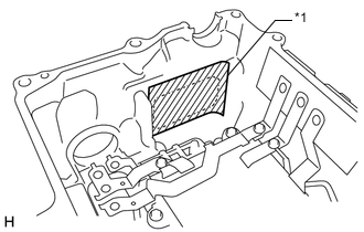
Apply seal packing (diameter: 2.0 to 3.0 mm (0.0787 to 0.118 in.)) in a continuous line to the locations shown in the illustration.
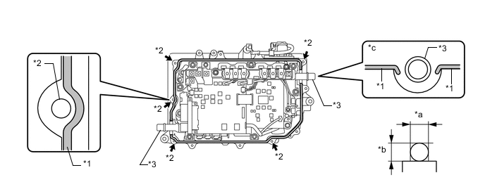
Text in Illustration *1 Seal Packing *2 Bolt Hole *3 Coolant Pipes - - *a 2.0 to 3.0 mm (0.0787 to 0.118 in.) *b 2.0 to 3.0 mm (0.0787 to 0.118 in.) *c Around Coolant Pipe - - Seal Packing Toyota Genuine Seal Packing 1282B, Three Bond 1282B or equivalent Note
-
Install the inverter case with condenser within 3 minutes of applying seal packing.
-
Tighten the bolts within 15 minutes of applying seal packing.
-
Keep the coolant pipes free from seal packing.
-
-
Install the inverter case with condenser.
-
Text in Illustration *1 Protective Tape Peel back the protective tape to the extent that the following steps can be performed.
Note
Do not touch or allow grease or oil to contact the sealing surfaces of the inverter case with condenser.
-
Temporarily install the inverter case with condenser to the hybrid vehicle converter kit so that the bus-bar (A) does not contact the protrusion of the inverter terminal sub-assembly w/ sensor (B).
Text in Illustration *1 Guide Pins - - Note
-
Make sure to align the guide pins correctly.
-
Check that the bus-bars of the hybrid converter kit overlap the bus-bars of the inverter case with condenser.
-
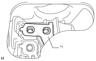
Make sure that the bus-bar (A) is not resting on the resin part of the inverter terminal with sensor sub-assembly as shown in the illustration.
Text in Illustration *1 Bus-bar (A) -
-
-
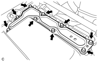
Temporarily install the inverter case with condenser with the 11 bolts.
- Torque:
- 4.0 N*m { 41 kgf*cm, 35 in.*lbf }
-
Fully tighten the 11 bolts.
- Torque:
- 9.2 N*m { 94 kgf*cm, 81 in.*lbf }
-
Install the 5 bolts to the bus-bars.
- Torque:
- 6.0 N*m { 61 kgf*cm, 53 in.*lbf }
Note
Do not touch the bus-bars.
-
Install the nut to the No. 2 engine room wire.
- Torque:
- 8.0 N*m { 82 kgf*cm, 71 in.*lbf }
Note
Check that the nut is not cross-threaded and the terminal is not loose.
-
Engage the 2 claws and close the terminal cover.
-
-
INSTALL INVERTER UNION GROMMET
-
Text in Illustration *1 Seal Packing Apply a light coat of seal packing to 2 new inverter union grommets.
Seal Packing Toyota Genuine Seal Packing 1282B, Three Bond 1282B or equivalent Note
-
Install the inverter union grommets within 60 minutes of installing the inverter case with condenser.
-
Apply a light coat of seal packing to the entire surface of the area shown in the illustration. If seal packing is applied excessively, it may seep out, however, sealing quality will not be affected.
-
Install the inverter union grommets within 3 minutes of applying seal packing.
-
-
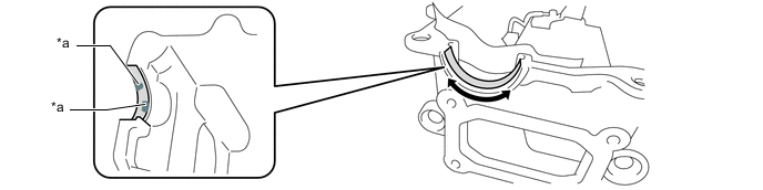
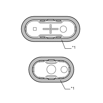
Text in Illustration *1 Coolant Pipe *2 Inverter Union Grommet *a Flange Push in the inverter union grommet until it passes over the flange of the coolant pipe.
Note
Do not damage the coolant pipes.
-
Text in Illustration *1 30 mm Socket Using a 30 mm socket, install the inverter union grommet.
-
Perform the same procedure to install the other inverter union grommet.
-
-
INSTALL NO. 1 AND NO. 2 INVERTER DRAIN PLUGS
Note
Do not touch or allow grease or oil to contact the sealing surfaces of the inverter case with condenser.
-
Text in Illustration *1 Aluminum Tape Make sure that the sealing surfaces of the No. 1 and No. 2 inverter drain plugs are covered with aluminum tape.
Note
If the sealing surfaces of the No. 1 and No. 2 inverter drain plugs are not covered with aluminum tape, do not use them as they cannot be securely installed with only seal packing.
-
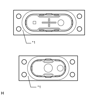
Text in Illustration *1 Release Film Remove the release film from the No. 1 and No. 2 inverter drain plugs.
-
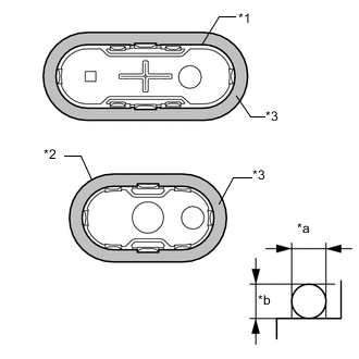
Text in Illustration *1 No. 1 Inverter Drain Plug *2 No. 2 Inverter Drain Plug *3 Seal Packing *a Approximately 3.0 mm (0.118 in.) *b Approximately 3.0 mm (0.118 in.) Apply seal packing (diameter: 3.0 mm (0.118 in.)) to new No. 1 and No. 2 inverter drain plugs.
Seal Packing Toyota Genuine Seal Packing 1282B, Three Bond 1282B or equivalent Note
-
Be sure to use the specified type of seal packing.
-
Install the No. 1 and No. 2 inverter drain plugs within 3 minutes of applying seal packing.
-
-
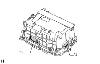
Text in Illustration *1 No. 1 Inverter Drain Plug *2 No. 2 Inverter Drain Plug Install the No. 1 and No. 2 inverter drain plugs to the inverter with converter assembly.
-
-
INSTALL INVERTER SIGNAL CONNECTOR COVER
-

Text in Illustration *1 Gasket Install the gasket to the inverter signal connector cover.
Tech Tips
Make sure that the protrusion (A) of the gasket is securely inserted into the groove of the inverter signal connector cover.
-
Clean the installation surface.
-
Text in Illustration *1 Inverter Signal Connector Cover Install the inverter signal connector cover with the 4 bolts.
- Torque:
- 6.0 N*m { 61 kgf*cm, 53 in.*lbf }
-
-
INSTALL INVERTER TERMINAL COVER
-
Text in Illustration *1 Protective Tape Remove the protective tape.
-
Temporarily install the inverter terminal cover with the 9 bolts to prevent any foreign objects or water from entering the inverter with converter assembly.
-
-
INSTALL INVERTER WITH CONVERTER ASSEMBLY
-
CHECK FOR COOLANT LEAK (for Inverter)
-
Remove the reserve tank cap.
CAUTION:
To avoid the danger of being burned, do not remove the reserve tank cap while the coolant for the inverter is still hot.
-
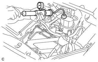
Install the radiator cap tester.
-
Pump the radiator cap tester to 122 kPa (1.2 kgf/ cm2, 17.7 psi), and then check that the pressure does not drop.
Tech Tips
If the pressure drops, check the hoses, radiator, water pump, inverter with converter, and hybrid vehicle transaxle assembly for leaks.
-
Reinstall the reserve tank cap.
-
-
OPERATION CHECK
Tech Tips
-
After the repair, check the operation as follows. Then check for DTCs again.
-
The current at the AMD terminal cannot be measured directly because of space limitations. Measure the current flowing at the auxiliary battery instead.
-
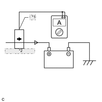
*1 Probe Direction *2 Current Flowing into Auxiliary Battery Connect the AC/DC 400 A probe to the positive (+) auxiliary battery cable.
-
Turn the power switch on (READY) and leave the vehicle as is until the electric current flowing into the auxiliary battery becomes 10 A or less.
-
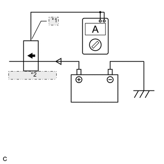
*1 Probe Direction *2 Current Flowing from Auxiliary Battery Change the orientation of the AC/DC400A probe.
-
Measure the current flowing from the auxiliary battery with the power switch on (READY), headlight position switch and blower motor switch in the HI position, and rear window defogger turned on.
Standard Current Item Switch Condition Specified Condition Current flowing from auxiliary battery Power switch on (READY)
(Headlight position switch and blower motor switch in HI position, rear window defogger on)
0 A or less
(No current from auxiliary battery)
-
Turn the power switch off.
-