HYBRID CONTROL SYSTEM, Diagnostic DTC:P0BEA-290, P0BEE-298, P1C3C-294, P1C3D-302, P1C4A-288, P1C4F-296, P1C6D-501, P1C6E-502
| DTC Code | DTC Name |
|---|---|
| P0BEA-290 | Drive Motor "A" Phase V Current Sensor Circuit Range / Performance |
| P0BEE-298 | Drive Motor "A" Phase V Current Sensor Circuit Range / Performance |
| P1C3C-294 | Drive Motor "A" Phase V Current Sensor Correlation |
| P1C3D-302 | Drive Motor "A" Phase W Current Sensor Correlation |
| P1C4A-288 | Drive Motor "A" Phase V Current Sensor Sub Circuit Range / Performance |
| P1C4F-296 | Drive Motor "A" Phase W Current Sensor Sub Circuit Range / Performance |
| P1C6D-501 | Drive Motor "A" Phase V Current Sensor Offset Range / Performance |
| P1C6E-502 | Drive Motor "A" Phase W Current Sensor Offset Range / Performance |
DESCRIPTION
The MG ECU located in the inverter with converter assembly monitors the motor inverter current sensors. P0BEA-290, P0BEE-298, P1C3C-294, P1C3D-302, P1C4A-288, P1C4F-296, P1C6D-501 and P1C6E-502 indicate malfunctions in current sensors, and they do not indicate malfunctions in the high-voltage system.
Tech Tips
The term "drive motor A" indicates MG2.
| DTC No. | INF Code | DTC Detection Condition | Trouble Area |
|---|---|---|---|
| P0BEA | 290 | Malfunction in motor inverter current sensor (phase V main sensor) | Inverter with converter assembly |
| P0BEE | 298 | Malfunction in motor inverter current sensor (phase W main sensor) | |
| P1C3C | 294 | Malfunction in motor inverter current sensor (performance problem or open phase V) | |
| P1C3D | 302 | Malfunction in motor inverter current sensor (performance problem or open phase W) | |
| P1C4A | 288 | Malfunction in motor inverter current sensor (phase V sub sensor) | |
| P1C4F | 296 | Malfunction in motor inverter current sensor (phase W sub sensor) | |
| P1C6D | 501 | Malfunction in motor inverter current sensor (phase V main and sub sensors offset) | |
| 1C6E | 502 | Malfunction in motor inverter current sensor (phase W main and sub sensors offset) |
PROCEDURE
-
CHECK DTC OUTPUT (HV)
-
Connect the intelligent tester to the DLC3.
-
Turn the power switch on (IG).
-
Enter the following menus: Powertrain / Hybrid Control / DTC.
-
Check if DTCs are output.
Result Result Proceed to P0BEA-290, P0BEE-298, P1C3C-294, P1C3D-302, P1C4A-288, P1C4F-296, P1C6D-501 or P1C6E-502 only is output. A P0A78-202 is output. B -
Turn the power switch off.
B 
GO TO DTC CHART (P0A78-202) Click here
A 
-
-
CHECK CONNECTOR CONNECTION CONDITION (INVERTER WITH CONVERTER ASSEMBLY CONNECTOR)
CAUTION:
Be sure to wear insulated gloves.
-
Check that the service plug grip is not installed.
Note
After removing the service plug grip, do not turn the power switch on (READY), unless instructed by the repair manual because this may cause a malfunction.
Note
Before disconnecting the connector, confirm that it is properly connected by checking that the locking claws are engaged and that the connector does not pull out.
-
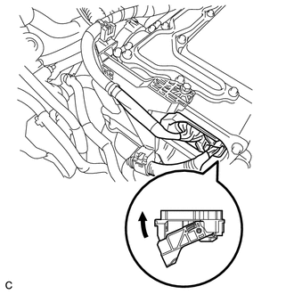
Check the connection of the low voltage connector of the inverter with converter assembly.
OK The connector is connected securely and there are no contact problems. Tech Tips
When connecting the connector, insert it with the locking lever in the raised position. Rotate the lever downward and make sure that the connector is pulled into its socket. When the locking lever is in its fully closed position, a click will be heard as its locking claws engage. After the click is heard, pull up on the connector to confirm that it is properly connected.
OK
REFER TO REPLACE INVERTER WITH CONVERTER ASSEMBLY PARTS Click here
NG
CONNECT SECURELY
-