HYBRID CONTROL SYSTEM, Diagnostic DTC:P3000-603
| DTC Code | DTC Name |
|---|---|
| P3000-603 | HV Battery Malfunction |
DESCRIPTION
The power management control ECU monitors its internal operation and detects the following malfunction.
| DTC No. | INF Code | DTC Detection Condition | Trouble Area |
|---|---|---|---|
| P3000 | 603 | The power management control ECU detects a HV battery cooling system error signal. |
|
PROCEDURE
-
CHECK DTC OUTPUT (HYBRID CONTROL)
-
Connect the intelligent tester to the DLC3.
-
Turn the power switch on (IG).
-
Enter the following menus: Powertrain / Hybrid Control / DTC.
-
Check if DTCs are output.
Result Result Proceed to P3000-603 only is output. A DTCs other than P3000-603 are also output. B -
Turn the power switch off.
B 
GO TO DTC CHART (HYBRID CONTROL SYSTEM) Click here
A 
-
-
CLEAN DUCT AND BLOWER
-
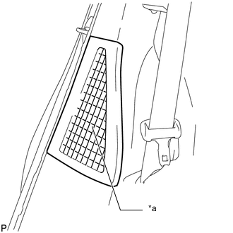
*1 Intake Port Check that the No. 1 hybrid battery intake duct and battery cooling blower are not disconnected, damaged, or clogged with foreign matter, and that the acoustical materials have not peeled.
Tech Tips
If anything is blocking the HV battery cooling system intake port, remove it.
-
Clean the No. 1 hybrid battery intake filter. (w/ No. 1 hybrid battery intake filter)
Note
-
Clean the No. 1 hybrid battery intake filter with an air blow gun. Do not use water or any other liquid.
-
Do not use a wire brush or any other type of brush as it may damage the No. 1 hybrid battery intake filter.
-
To prevent removed foreign matter from entering the HV battery, make sure to remove the No. 1 hybrid battery intake filter when cleaning it.
-
NEXT
-
-
CHECK FREEZE FRAME DATA
-
Connect the intelligent tester to the DLC3.
-
Turn the power switch on (IG).
-
Enter the following menus: Powertrain / Hybrid Control / Trouble Codes.
-
Read the freeze frame data of DTC P3000-603.
Note
Although freeze frame data is recorded before and after a DTC is stored, for this step it is only necessary to read the freeze flame data recorded before "0s" (when the DTC was stored).
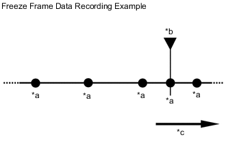
*a Freeze Frame Data Recorded *b DTC Stored *c Time Result Result Proceed to Other than below A The difference between the value of "VL-Voltage before Boosting" and the total of "Battery Block Vol -V01 to -V14" is 10 V or more. B
B 
REPLACE BATTERY SMART UNIT Click here
A
-
-
CHECK FREEZE FRAME DATA
-
Connect the intelligent tester to the DLC3.
-
Turn the power switch on (IG).
-
Enter the following menus: Powertrain / Hybrid Control / Trouble Codes.
-
Read the freeze frame data of DTC P3000-603.
Note
Although freeze frame data is recorded before and after a DTC is stored, for this step it is only necessary to read the freeze flame data recorded at "0s" (when the DTC was stored).
Result Result Proceed to Other than below A The value of any of "Temp of Batt TB1 to TB3" is 80°C (176°F) or more. B -
Turn the power switch off.
B
REPLACE POWER MANAGEMENT CONTROL ECU Click here
A
-
-
READ VALUE USING INTELLIGENT TESTER
-
Connect the Intelligent tester to the DLC3.
-
Turn the power switch on (IG).
-
Enter the following menus: Powertrain / Hybrid Control / Data List / "Temp of Batt TB1 to TB3".
-
According to the display on the intelligent tester, read the Data List and check that the value of each "Temp of Batt TB1 to TB3" is 40°C (104°F) or less.
Tech Tips
If the value of any of "Temp of Batt TB1 to TB3" is more than 40°C (104°F), turn the ignition switch off and wait until the values to decrease to 40°C (104°F) or less before continuing this procedure.
-
Enter the following menus: Powertrain / Hybrid Control / Data List / "Battery Block Vol - V01 to V14".
-
According to the display on the intelligent tester, read the Data List and check the value of each "Battery Block Vol-V01 to V14" with the power switch on (IG).
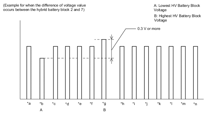
*a Battery Block Vol -V01 *b Battery Block Vol -V02 *c Battery Block Vol -V03 *d Battery Block Vol -V04 *e Battery Block Vol -V05 *f Battery Block Vol -V06 *g Battery Block Vol -V07 *h Battery Block Vol -V08 *i Battery Block Vol -V09 *j Battery Block Vol -V10 *k Battery Block Vol -V11 *l Battery Block Vol -V12 *m Battery Block Vol -V13 *n Battery Block Vol -V14 Result Result Proceed to Other than below A The difference between the lowest and highest HV battery block voltage is 0.3 V or more. B -
Turn the power switch off.
A
COMPLETED
B
-
-
REPLACE POWER MANAGEMENT CONTROL ECU
-
Replace the power management control ECU Click here.
NEXT
REPLACE HV BATTERY Click here
-
-
REPLACE BATTERY SMART UNIT
NEXT
REPLACE HV BATTERY Click here