THROTTLE BODY INSTALLATION
PROCEDURE
-
INSTALL THROTTLE BODY ASSEMBLY
-
Type A:
-
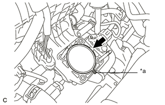
Text in Illustration *a Protrusion Install a new gasket to the intake manifold.
Tech Tips
Orient the protrusion of the gasket as shown in the illustration.
-
Install the throttle body assembly to the intake manifold with the 2 bolts and 2 nuts.
- Torque:
- 10 N*m { 102 kgf*cm, 7 ft.*lbf }
-
Connect the No. 1 water by-pass hose and No. 2 water by-pass hose to the throttle body assembly and slide the 2 clips to secure them.
-
Connect the throttle body assembly connector.
-
-
Type B:
-

Text in Illustration *a Protrusion Install a new gasket to the intake manifold.
Tech Tips
Orient the protrusion of the gasket as shown in the illustration.
-
Install the throttle body assembly to the intake manifold with the 4 bolts.
- Torque:
- 10 N*m { 102 kgf*cm, 7 ft.*lbf }
-
Connect the No. 1 water by-pass hose and No. 2 water by-pass hose to the throttle body assembly and slide the 2 clips to secure them.
-
Connect the throttle body assembly connector.
-
-
-
INSTALL AIR CLEANER HOSE ASSEMBLY
-
Install the air cleaner hose assembly to the throttle body assembly and tighten the hose clamp.
-
Connect the ventilation hose to the cylinder head cover sub-assembly and slide the clip to secure it.
-
-
INSTALL AIR CLEANER CASE
-
Install the air cleaner case with the 2 bolts.
- Torque:
- 7.0 N*m { 71 kgf*cm, 62 in.*lbf }
-
Connect the water hose to the clamp.
-
Install the air cleaner filter element sub-assembly to the air cleaner case.
-
-
INSTALL INLET AIR CLEANER ASSEMBLY
-
Install the inlet air cleaner assembly to the air cleaner case.
-
Install the 2 bolts to the inlet air cleaner assembly.
- Torque:
- 7.0 N*m { 71 kgf*cm, 62 in.*lbf }
-
Engage the wire harness clamp to the inlet air cleaner assembly.
-
-
INSTALL WATER HOSE HOSE CLAMP
-
Install the water hose hose clamp with the 2 clips.
-
Connect the water by-pass hose to the water hose hose clamp.
-
-
INSTALL AIR CLEANER CAP SUB-ASSEMBLY
-
Engage the 2 clamps to install the air cleaner cap sub-assembly.
-
Connect the air cleaner hose assembly to the air cleaner cap sub-assembly and tighten the hose clamp.
-
Connect the water hose to the clamp.
-
Connect the mass air flow meter connector and engage the wire harness clamp.
-
-
ADD COOLANT (for Engine)
-
INSPECT FOR COOLANT LEAK (for Engine)
-
INSTALL NO. 2 CYLINDER HEAD COVER
-
INSTALL RADIATOR SUPPORT OPENING COVER
-
PERFORM INITIALIZATION
Note
Be sure to perform this procedure after reassembling the throttle body assembly, removing and reinstalling any throttle body assembly component or replacing the ECM.
-
Disconnect the cable from the negative (-) auxiliary battery terminal. Wait at least 60 seconds and reconnect the cable.
-
Connect the intelligent tester to the DLC3 and clear the DTCs.
-
w/ EGR System: Click here
-
w/o EGR System: Click here
-
-
Set the vehicle to inspection mode Click here.
-
Start the engine without operating the accelerator pedal and check that the MIL is not illuminated and that the idle speed is within the specified range when the air conditioning is switched off after the engine is warmed up.
Standard Condition Engine Idle Speed A/C switched off 950 to 1050 rpm Note
-
If the accelerator pedal is operated, perform the above steps again.
-
Be sure to perform this step with all accessories off.
-
Make sure that park (P) is selected.
-
-
Perform a road test and confirm that there are no abnormalities.
-