MAYDAY SWITCH INSPECTION
PROCEDURE
-
INSPECT MAP LIGHT ASSEMBLY
-
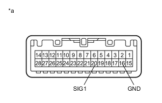
Text in Illustration *a Component without harness connected
(Map Light Assembly)
Inspect the operation of the emergency call switch.
-
Measure the resistance according to the value(s) in the table below.
Standard Resistance Tester Connection Condition Specified Condition 20 (SIG1) - 16 (GND) Emergency call switch not operated 410 to 414 Ω 20 (SIG1) - 16 (GND) Emergency call switch operated 81 to 83 Ω
-
-
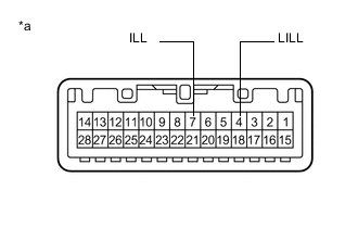
Text in Illustration *a Component without harness connected
(Map Light Assembly)
Inspect the illumination for the emergency call switch.
-
Connect 4 1.5 V dry-cell batteries in series.
-
Connect a positive (+) lead from the batteries to terminal 7 (ILL), and a negative (-) lead to terminal 4 (LILL) of the map light assembly connector.
-
Check if the illumination for the emergency call switch comes on.
OK Illumination for the emergency call switch comes on.
-
-
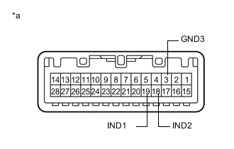
Text in Illustration *a Component without harness connected
(Map Light Assembly)
Inspect the indicator of the emergency call switch.
-
Connect 2 1.5 V dry-cell batteries in series.
-
Connect a positive (+) lead to terminal 19 (IND1) or 18 (IND2), and a negative (-) lead to terminal 3 (GND3) of the map light assembly connector.
-
Check if the red and green indicators come on.
OK The red indicator comes on when the positive (+) lead from the batteries is connected to terminal 19 (IND1) and the negative (-) lead is connected to terminal 3 (GND3). The green indicator comes on when the positive (+) lead from the batteries is connected to terminal 18 (IND2) and the negative (-) lead to is connected to terminal 3 (GND3).
-
-