NAVIGATION SYSTEM Stereo Jack Adapter Light does not Illuminate
DESCRIPTION
Power is supplied to the No. 1 stereo jack adapter assembly illumination from the radio receiver assembly.
WIRING DIAGRAM
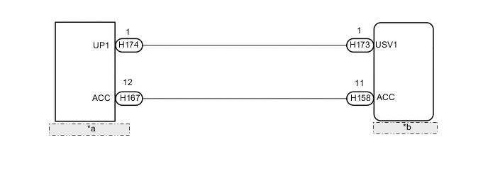
| *a | No. 1 Stereo Jack Adapter Assembly |
| *b | Radio Receiver Assembly |
CAUTION / NOTICE / HINT
Note
Depending on the parts that are replaced during vehicle inspection or maintenance, performing initialization, registration or calibration may be needed. Refer to Precaution for Navigation System Click here.
PROCEDURE
-
CHECK HARNESS AND CONNECTOR (NO. 1 STEREO JACK ADAPTER ASSEMBLY ILLUMINATION POWER SOURCE)
-
Disconnect the H174 and H167 No. 1 stereo jack adapter assembly connectors.
-
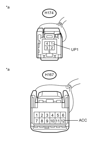
Text in Illustration *a Front view of wire harness connector
(to No. 1 Stereo Jack Adapter Assembly)
Measure the voltage according to the value(s) in the table below.
Standard Voltage Tester Connection Condition Specified Condition H174-1 (UP1) - Body ground Power switch on (ACC) 5 V H167-12 (ACC) - Body ground Power switch on (ACC) 11 to 14 V
OK 
REPLACE NO. 1 STEREO JACK ADAPTER ASSEMBLY Click here
NG 
-
-
CHECK HARNESS AND CONNECTOR (RADIO RECEIVER ASSEMBLY - NO. 1 STEREO JACK ADAPTER ASSEMBLY)
-
Disconnect the H173 radio receiver assembly connector.
-
Disconnect the H174 No. 1 stereo jack adapter assembly connector.
-
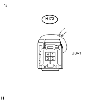
Text in Illustration *a Front view of wire harness connector
(to Radio Receiver Assembly)
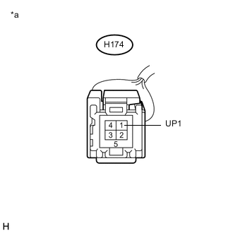
Text in Illustration *a Front view of wire harness connector
(to No. 1 Stereo Jack Adapter Assembly)
Measure the resistance according to the value(s) in the table below.
Standard Resistance Tester Connection Condition Specified Condition H174-1 (UP1) - H173-1 (USV1) Always Below 1 Ω H174-1 (UP1) - Body ground Always 10 kΩ or higher
NG
REPAIR OR REPLACE HARNESS OR CONNECTOR
OK
-
-
CHECK HARNESS AND CONNECTOR (RADIO RECEIVER ASSEMBLY - NO. 1 STEREO JACK ADAPTER ASSEMBLY)
-
Disconnect the H158 radio receiver assembly connector.
-
Disconnect the H167 No. 1 stereo jack adapter assembly connector.
-
Measure the resistance according to the value(s) in the table below.
Standard Resistance Tester Connection Condition Specified Condition H158-11 (ACC) - H167-12 (ACC) Always Below 1 Ω H158-11 (ACC) - Body ground Always 10 kΩ or higher
OK
REPLACE RADIO RECEIVER ASSEMBLY Click here
NG
REPAIR OR REPLACE HARNESS OR CONNECTOR
-