NAVIGATION SYSTEM, Diagnostic DTC:B1321, B1322, B1323, B1324, B1563
| DTC Code | DTC Name |
|---|---|
| B1321 | Lost Communication with EMV |
| B1322 | Lost Communication with Display |
| B1323 | Lost Communication with Haptic Device |
| B1324 | Lost Communication with Meter |
| B1563 | Haptic Device Disconnected |
DESCRIPTION
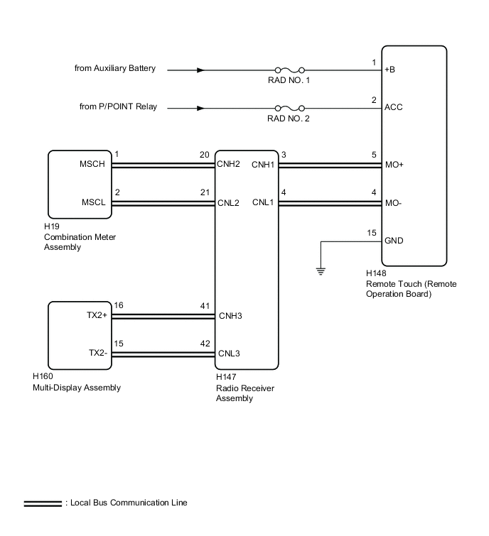
These DTCs are stored when communication between the radio receiver assembly and remote touch or combination meter assembly is not possible.
| DTC No. | DTC Detection Condition | Trouble Area |
|---|---|---|
| B1321 | The components connected via local bus communication do not receive the registration information signal from the radio receiver assembly for 30 seconds or more |
|
| B1322 | The radio receiver assembly does not receive the registration information signal from the remote touch (remote operation board) for 30 seconds or more |
|
| B1323 | The radio receiver assembly does not receive the registration information signal from the remote touch (remote operation board) for 30 seconds or more |
|
| B1324 | After the radio receiver assembly receives a registration information signal, which is sent by the combination meter assembly when the power switch is turned on (IG), 1 or more times, the radio receiver assembly does not receive the signal for 30 seconds or more |
|
| B1563 | The remote touch (remote operation board) is/was not connected while the power switch is/was on (ACC) or on (IG) |
|
WIRING DIAGRAM
CAUTION / NOTICE / HINT
Note
-
Inspect the fuses for circuits related to this system before performing the following procedure.
-
Depending on the parts that are replaced during vehicle inspection or maintenance, performing initialization, registration or calibration may be needed. Refer to Precaution for Navigation System Click here.
-
After turning the power switch off, waiting time may be required before disconnecting the cable from the negative (-) auxiliary battery terminal. Therefore, make sure to read the disconnecting the cable from the negative (-) auxiliary battery terminal notices before proceeding with work Click here.
PROCEDURE
-
CHECK HARNESS AND CONNECTOR (RADIO RECEIVER ASSEMBLY - REMOTE TOUCH (REMOTE OPERATION BOARD))
-
Disconnect the cable from the negative (-) auxiliary battery terminal.
-
Disconnect the H147 radio receiver assembly connector.
-
Disconnect the H148 remote touch (remote operation board) connector.
-
Measure the resistance according to the value(s) in the table below.
Standard Resistance Tester Connection Condition Specified Condition H147-3 (CNH1) - H148-5 (MO+) Always Below 1 Ω H147-4 (CNL1) - H148-4 (MO-) Always Below 1 Ω H147-3 (CNH1) or H148-5 (MO+) - Body ground Always 10 kΩ or higher H147-4 (CNL1) or H148-4 (MO-) - Body ground Always 10 kΩ or higher H148-5 (MO+) - H148-4 (MO-) Always 10 kΩ or higher H148-5 (MO+) - H148-1 (+B) Cable disconnected from negative (-) auxiliary battery terminal 6 kΩ or higher H148-4 (MO-) - H148-1 (+B) Cable disconnected from negative (-) auxiliary battery terminal 6 kΩ or higher
NG 
REPAIR OR REPLACE HARNESS OR CONNECTOR
OK 
-
-
CHECK HARNESS AND CONNECTOR (RADIO RECEIVER ASSEMBLY - COMBINATION METER ASSEMBLY)
-
Disconnect the cable from the negative (-) auxiliary battery terminal.
-
Disconnect the H147 radio receiver assembly connector.
-
Disconnect the H19 combination meter assembly connector.
-
Measure the resistance according to the value(s) in the table below.
Standard Resistance Tester Connection Condition Specified Condition H147-20 (CNH2) - H19-1 (MSCH) Always Below 1 Ω H147-21 (CNL2) - H19-2 (MSCL) Always Below 1 Ω H147-20 (CNH2) or H19-1 (MSCH) - Body ground Always 10 kΩ or higher H147-21 (CNL2) or H19-2 (MSCL) - Body ground Always 10 kΩ or higher H19-1 (MSCH) - H19-2 (MSCL) Always 10 kΩ or higher H19-1 (MSCH) - H148-1 (+B) Cable disconnected from negative (-) auxiliary battery terminal 6 kΩ or higher H19-2 (MSCL) - H148-1 (+B) Cable disconnected from negative (-) auxiliary battery terminal 6 kΩ or higher
NG
REPAIR OR REPLACE HARNESS OR CONNECTOR
OK
-
-
CHECK HARNESS AND CONNECTOR (RADIO RECEIVER ASSEMBLY - MULTI-DISPLAY ASSEMBLY)
-
Disconnect the cable from the negative (-) auxiliary battery terminal.
-
Disconnect the H147 radio receiver assembly connector.
-
Disconnect the H160 multi-display assembly connector.
-
Measure the resistance according to the value(s) in the table below.
Standard Resistance Tester Connection Condition Specified Condition H147-41 (CNH3) - H160-16 (TX2+) Always Below 1 Ω H147-42 (CNL3) - H160-15 (TX2-) Always Below 1 Ω H147-41 (CNH3) or H160-16 (TX2+) - Body ground Always 10 kΩ or higher H147-42 (CNL3) or H160-15 (TX2-) - Body ground Always 10 kΩ or higher H160-16 (TX2+) - H160-15 (TX2-) Always 10 kΩ or higher H160-16 (TX2+) - H148-1 (+B) Cable disconnected from negative (-) auxiliary battery terminal 6 kΩ or higher H160-15 (TX2-) - H148-1 (+B) Cable disconnected from negative (-) auxiliary battery terminal 6 kΩ or higher
NG
REPAIR OR REPLACE HARNESS OR CONNECTOR
OK
-
-
CHECK HARNESS AND CONNECTOR (REMOTE TOUCH (REMOTE OPERATION BOARD) POWER SOURCE)
-
Disconnect the H148 remote touch (remote operation board) connector.
-
Measure the resistance according to the value(s) in the table below.
Standard Resistance Tester Connection Condition Specified Condition H148-15 (GND) - Body ground Always Below 1 Ω -
Measure the voltage according to the value(s) in the table below.
Standard Voltage Tester Connection Condition Specified Condition H148-1 (+B) - H148-15 (GND) Power switch off 11 to 14 V H148-2 (ACC) - H148-15 (GND) Power switch on (ACC) 11 to 14 V
NG
REPAIR OR REPLACE HARNESS OR CONNECTOR
OK
-
-
INSPECT COMBINATION METER ASSEMBLY
-
Remove the combination meter assembly Click here.
-
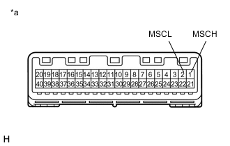
*a Component without harness connected
(Combination Meter Assembly)
Measure the resistance according to the value(s) in the table below.
Standard Resistance Tester Connection Condition Specified Condition 1 (MSCH) - 2 (MSCL) Always 108 to 132 Ω
NG
REPLACE COMBINATION METER ASSEMBLY Click here
OK
-
-
INSPECT MULTI-DISPLAY ASSEMBLY
-
Remove the multi-display assembly Click here.
-
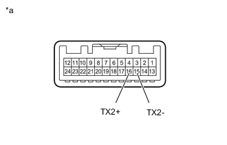
*a Component without harness connected
(Multi-Display Assembly)
Measure the resistance according to the value(s) in the table below.
Standard Resistance Tester Connection Condition Specified Condition 15 (TX2-) - 16 (TX2+) Always 108 to 132 Ω
NG
REPLACE MULTI-DISPLAY ASSEMBLY Click here
OK
-
-
INSPECT RADIO RECEIVER ASSEMBLY
-
Remove the radio receiver assembly Click here.
-
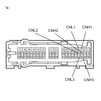
*a Component without harness connected
(Radio Receiver Assembly)
Measure the resistance according to the value(s) in the table below.
Standard Resistance Tester Connection Condition Specified Condition 3 (CNH1) - 4 (CNL1) Always 108 to 132 Ω 20 (CNH2) - 21 (CNL2) Always 108 to 132 Ω 41 (CNH3) - 42 (CNL3) Always 108 to 132 Ω 3 (CNH1) - 20 (CNH2) Always Below 1 Ω 4 (CNL1) - 21 (CNL2) Always Below 1 Ω 3 (CNH1) - 41 (CNH3) Always Below 1 Ω 4 (CNL1) - 42 (CNL3) Always Below 1 Ω
NG
REPLACE RADIO RECEIVER ASSEMBLY Click here
OK
-
-
REMOTE TOUCH SELF CHECK (REMOTE TOUCH SWITCH KNOB FEEDBACK FORCE GENERATION CHECK)
-
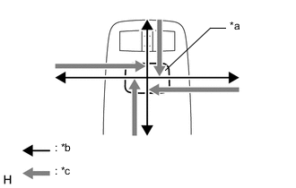
Text in Illustration *a Switch Knob *b Control Direction *c Feedback Force Check the remote touch switch knob feedback force.
-
Move the remote touch switch knob up, down, right and left to check that feedback force is generated.
OK Feedback force is generated. Tech Tips
When the power switch is turned on (ACC), feedback force is generated. When the power switch is turned off, feedback force is not generated, and the remote touch switch knob will move freely.
-
NG
REPLACE REMOTE OPERATION BOARD Click here
OK
-
-
REPLACE COMBINATION METER ASSEMBLY
-
Replace the combination meter assembly with a new or known good one Click here.
-
Clear the DTCs Click here.
-
Recheck for DTCs and check that no DTCs are output.
OK No DTCs are output.
NG 
REPLACE MULTI-DISPLAY ASSEMBLY Click here
OK
-
-
CHECK METER / GAUGE SYSTEM
-
Turn the power switch on (IG) and wait 30 seconds.
-
Operate the steering pad switch assembly and check that the audio tab is displayed on the multi-information display in the combination meter assembly and the audio system can be operated normally.
OK Audio system returns to normal.
OK
END
NG
-
-
REPLACE MULTI-DISPLAY ASSEMBLY
-
Replace the multi-display assembly with a new or known good one Click here.
-
Clear the DTCs Click here.
-
Recheck for DTCs and check that no DTCs are output.
OK No DTCs are output.
NG
REPLACE RADIO RECEIVER ASSEMBLY Click here
OK
-
-
CHECK MULTI-DISPLAY SYSTEM
-
Turn the power switch on (IG) and wait 30 seconds.
-
Check that the screen display is normal.
OK Screen display is normal.
OK
END
NG
-
-
REPLACE RADIO RECEIVER ASSEMBLY
-
Replace the radio receiver assembly with a new or known good one Click here.
-
Clear the DTCs Click here.
-
Recheck for DTCs and check that no DTCs are output.
OK No DTCs are output.
NG
REPLACE REMOTE OPERATION BOARD Click here
OK
-
-
CHECK REMOTE TOUCH
-
Turn the power switch on (IG) and wait 30 seconds.
-
Check that the navigation system can be operated normally using the remote touch.
OK Navigation system returns to normal.
OK
END
NG
REPLACE REMOTE OPERATION BOARD Click here
-