NAVIGATION SYSTEM TERMINALS OF ECU
Tech Tips
Check from the rear of the connector while it is connected to the components.
-
RADIO RECEIVER ASSEMBLY
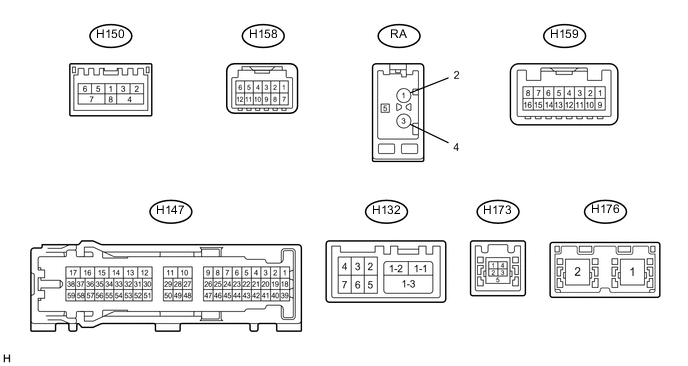
Terminal No. (Symbol) Wiring Color Terminal Description Condition Specified Condition H147-1 (CANH) R CAN communication signal - - H147-2 (CANL) W CAN communication signal - - H147-3 (CNH1) B Local bus communication signal - - H147-4 (CNL1) W Local bus communication signal - - H147-7 (TX1+) SB AVC-LAN communication signal - - H147-8 (TX1-) P AVC-LAN communication signal - - H147-10 (VMTF) - H147-12 (GND1) GR - W-B Visual mute signal Power switch on (ACC)
Screen display changes
3.5 V or higher
→ Below 1 V
→ 3.5 V or higher
H147-12 (GND1) - Body ground W-B - Body ground Ground Always Below 1 V H147-13 (ILL-) - H147-12 (GND1) B - W-B Illumination signal Light control switch off Below 1 V Light control switch in tail or head position Pulse generation H147-14 (ILL+) - H147-12 (GND1) G - W-B Illumination signal Light control switch off Below 1 V Power switch off
Light control switch in tail or head position
11 to 14 V H147-15 (IG) - H147-12 (GND1) V - W-B Power source (IG) Power switch off Below 1 V Power switch on (IG) 11 to 14 V H147-16 (ACC1) - H147-12 (GND1) B - W-B Power source (ACC) Power switch off Below 1 V Power switch on (ACC) 11 to 14 V H147-17 (+B1) - H147-12 (GND1) V - W-B Power source (+B) Power switch off 11 to 14 V H147-18 (V+) - H147-12 (GND1) R - W-B Video signal Power switch on (READY)
Reverse (R) selected
Camera lens not covered, displaying an image
Pulse generation (Refer to waveform 1) Power switch on (READY)
Reverse (R) selected
Camera lens covered, blacking out screen
Pulse generation (Refer to waveform 2) H147-19 (V-) - H147-12 (GND1) W - W-B Ground Always Below 1 V H147-20 (CNH2) G Local bus communication signal - - H147-21 (CNL2) Y Local bus communication signal - - H147-27 (MIN+) - H147-12 (GND1) G - W-B*1
Y - W-B*2
Microphone voice signal See "Check Microphone" in Operation Check Click here
- H147-28 (SGND) - Body ground Shield - Body ground Shield ground Always Below 1 V H147-29 (MACC) - H147-12 (GND1)*2 B - W-B Microphone power supply Power switch off Below 1 V Power switch on (ACC) 4 to 6 V H147-30 (SW1) - H147-32 (SWG) GR - W Steering pad switch signal No switch pushed 2.97 to 3.56 V Seek+ switch pushed 0.27 to 0.35 V Seek- switch pushed 0.86 to 1.03 V Volume+ switch pushed 1.51 to 1.79 V Volume- switch pushed 2.22 to 2.66 V H147-31 (SW2) - H147-32 (SWG) G - W Steering pad switch signal No switch pushed 2.97 to 3.56 V MODE switch pushed 0.27 to 0.35 V On hook switch pushed 0.86 to 1.03 V Off hook switch pushed 1.51 to 1.79 V Voice switch pushed 2.22 to 2.66 V H147-32 (SWG) - Body ground W - Body ground Steering pad switch signal Always Below 1 V H147-39 (CA+) - H147-12 (GND1) B - W-B Television camera power supply Power switch on (ACC) 5.5 to 7.05 V H147-40 (CGND) - Body ground Shield - Body ground Shield ground Always Below 1 V H147-45 (TX3+) P AVC-LAN communication signal - - H147-46 (TX3-) G AVC-LAN communication signal - - H147-48 (MIN-) - Body ground R - Body ground*1
L - Body ground*2
Microphone voice signal See "Check Microphone" in Operation Check Click here
- H147-49 (SNS2) - H147-12 (GND1) V - W-B Microphone connection detection signal Always Below 1 V H147-55 (PKB) - H147-12 (GND1) R - W-B Parking brake signal See "Check Vehicle Signal" in Operation Check Click here
- H147-56 (SPD) - H147-12 (GND1) V - W-B Vehicle speed signal See "Check Vehicle Signal" in Operation Check Click here
- H159-5 (AGND) - Body ground Shield - Body ground Shield ground Always Below 1 V H159-6 (VV+) - H147-12 (GND1) B - W-B Video signal External device system playing
(when stereo jack used)
A waveform synchronized with video signals is output H159-7 (VAR+) - H159-15 (VA-) R - B Sound signal (Right) External device system playing
(when stereo jack used)
A waveform synchronized with sound signals is output H159-8 (VAL+) - H159-15 (VA-) W - B Sound signal (Left) External device system playing
(when stereo jack used)
A waveform synchronized with sound signals is output H159-13 (SG) - Body ground Shield - Body ground Shield ground Always Below 1 V H159-14 (VV-) - H147-12 (GND1) W - W-B Video signal ground Always Below 1 V H159-15 (VA-) - H147-12 (GND1) B - W-B Ground Always Below 1 V H159-16 (ADPG) - H147-12 (GND1) BR - W-B External device connection detection signal External device connected Below 1 V External device not connected 2.1 to 3 V H150-1 (WUO) W MOST communication wake-up signal - - H150-2 (MI+) B MOST communication signal - - H150-3 (MI-) B MOST communication signal - - H150-4 (SLDI) B Shield - - H150-5 (MO+) B MOST communication signal - - H150-6 (MO-) B MOST communication signal - - H150-7 (SLDO) B Shield - - H132-1-1 (USB (USB-))*1 B USB communication line - - H132-1-2 (USB (USB+))*1 B USB communication line - - H132-1-3 (USB (USBS)) - Body ground*1 B - Body ground Shield ground Always Below 1 V H132-2 (USBG) - Body ground*1 W - Body ground Ground Always Below 1 V H132-3 (VOT+) - H147-12 (GND1)*1 W - W-B Sent voice signal Calling while using operator service A waveform synchronized with sent voice signals is output H132-4 (USBV) - H147-12 (GND1)*1 W - W-B Telematics transceiver power supply Power switch off Below 1 V Power switch on (ACC) 4.75 to 5.25 V H132-5 (VOT-) - H147-12 (GND1)*1 R - W-B Sent voice signal Calling while using operator service A waveform synchronized with sent voice signals is output H132-6 (VOR-) - H147-12 (GND1)*1 B - W-B Receive voice signal Receiving a call while using operator service A waveform synchronized with receive voice signals is output H132-7 (VOR+) - H147-12 (GND1)*1 G - W-B Receive voice signal Receiving a call while using operator service A waveform synchronized with receive voice signals is output H158-7 (GND2) - Body ground LG - Body ground Ground Always Below 1 V H158-12 (+B) - H147-12 (GND1) G - W-B Power source (+B) Power switch off 11 to 14 V H173-1 (USV1) - Power source - - H173-2 (US1-) - Data signal - - H173-3 (US1+) - Data signal - - H173-4 (UOD1) - Ground - - H173-5 (USG1) - Shield ground - - H176-1 (GVIF) B Video signal (Digital) - - H176-2 (GVIF) B Video signal (Digital) - - RA-5 (ANT+) - H147-12 (GND1) - - W-B Power source of antenna Power switch on (ACC)
Radio switch on and AM or FM selected
11 to 14 V
-
*1: w/ Manual (SOS) Switch
-
*2: w/o Manual (SOS) Switch
-
Reference (Oscilloscope waveform):
-
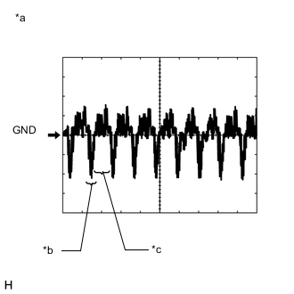
Text in Illustration *a Waveform 1 (camera lens not covered, displaying an image) *b Synchronization Signal *c Video Waveform Waveform 1 (camera lens is not covered, displaying an image)
Item Content Measurement terminal H147-18 (V+) - H147-12 (GND1) Measurement setting 200 mV/DIV., 50 μsec./DIV. Condition Power switch on (READY), reverse (R) selected Tech Tips
-
The video waveform changes according to the image sent by the rear television camera assembly.
-
The video waveform is constantly when the power switch is on (ACC).
-
-
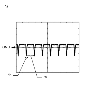
Text in Illustration *a Waveform 2 (camera lens covered, blacking out the screen) *b Synchronization Signal *c Video Waveform Waveform 2 (camera lens is covered, blacking out the screen)
Item Content Measurement terminal H147-18 (V+) - H147-12 (GND1) Measurement setting 200 mV/DIV., 50 μsec./DIV. Condition Power switch on (READY), reverse (R) selected Tech Tips
-
The video waveform changes according to the image sent by the rear television camera assembly.
-
The video waveform is constantly when the power switch is on (ACC).
-
-
-
-
STEREO COMPONENT AMPLIFIER ASSEMBLY
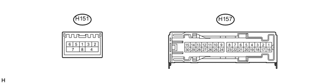
Terminal No. (Symbol) Wiring Color Terminal Description Condition Specified Condition H157-1 (+B) - H157-3 (GND) R - W-B Power source (+B) Power switch off 11 to 14 V H157-2 (TMUT) - Body ground*1 L - Body ground Mute signal Audio system playing Above 3.5 V Emergency call mode Below 1 V H157-3 (GND) - Body ground W-B - Body ground Ground Always Below 1 V H157-4 (ML+) - H157-3 (GND) P - W-B Sound signal (Front Left) Audio system playing A waveform synchronized with sound signals is output H157-5 (MR+) - H157-3 (GND) LG - W-B Sound signal (Front Right) Audio system playing A waveform synchronized with sound signals is output H157-6 (WF1+) - H157-3 (GND) W - W-B Sound signal (Woofer) Audio system playing A waveform synchronized with sound signals is output H157-7 (CTR+) - H157-3 (GND) BR - W-B Sound signal (Front Center) Audio system playing A waveform synchronized with sound signals is output H157-8 (WF2+) - H157-3 (GND)*2 G - W-B Sound signal (Woofer) Audio system playing A waveform synchronized with sound signals is output H157-12 (FL+) - H157-3 (GND) R - W-B Sound signal (Front Left) Audio system playing A waveform synchronized with sound signals is output H157-13 (FR+) - H157-3 (GND) G - W-B Sound signal (Front Right) Audio system playing A waveform synchronized with sound signals is output H157-14 (RL+) - H157-3 (GND) G - W-B Sound signal (Rear Left) Audio system playing A waveform synchronized with sound signals is output H157-15 (RR+) - H157-3 (GND) SB - W-B Sound signal (Rear Right) Audio system playing A waveform synchronized with sound signals is output H157-16 (+B2) - H157-3 (GND) B - W-B Power source (+B) Power switch off 11 to 14 V H157-17 (SPD) - H157-3 (GND) V - W-B Vehicle speed signal Power switch on (IG)
Wheel being rotated
Pulse generation H157-18 (GND2) - Body ground W-B - Body ground Ground Always Below 1 V H157-19 (ML-) - H157-3 (GND) V - W-B Sound signal (Front Left) Audio system playing A waveform synchronized with sound signals is output H157-20 (MR-) - H157-3 (GND) L - W-B Sound signal (Front Right) Audio system playing A waveform synchronized with sound signals is output H157-21 (WF1-) - H157-3 (GND)*3 BR - W-B Sound signal (Woofer) Audio system playing A waveform synchronized with sound signals is output H157-22 (CTR-) - H157-3 (GND) GR - W-B Sound signal (Front Center) Audio system playing A waveform synchronized with sound signals is output H157-27 (FL-) - H157-3 (GND) W - W-B Sound signal (Front Left) Audio system playing A waveform synchronized with sound signals is output H157-28 (FR-) - H157-3 (GND) BR - W-B Sound signal (Front Right) Audio system playing A waveform synchronized with sound signals is output H157-29 (RL-) - H157-3 (GND) BR - W-B Sound signal (Rear Left) Audio system playing A waveform synchronized with sound signals is output H157-30 (RR-) - H157-3 (GND) BE - W-B Sound signal (Rear Right) Audio system playing A waveform synchronized with sound signals is output H151-2 (MI+) B MOST communication signal - - H151-3 (MI-) B MOST communication signal - - H151-4 (SLDI) B Shield ground - - H151-5 (MO+) B MOST communication signal - - H151-6 (MO-) B MOST communication signal - - H151-7 (SLDO) B Shield ground - - H151-8 (WUI) W MOST communication wake-up signal - -
-
*1: w/ Manual (SOS) Switch
-
*2: for 13 Speakers
-
*3: for 10 Speakers
-
-
MULTI-DISPLAY
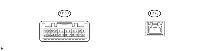
Terminal No. (Symbol) Wiring Color Terminal Description Condition Specified Condition H160-2 (ILL) - H160-13 (GND1) SB - W-B Illumination signal Light control switch off Below 1 V Power switch off
Light control switch in tail or head position
11 to 14 V H160-7 (TX+) P AVC-LAN communication signal - - H160-11 (VMTI) - H160-13 (GND1) GR - W-B Visual mute signal When image on display switches 3.5 V or higher
→ Below 1 V
→ 3.5 V or higher
H160-12 (B) - H160-13 (GND1) P- W-B Power source (+B) Power switch off 11 to 14 V H160-13 (GND1) - Body ground W-B - Body ground Ground Always Below 1 V H160-19 (TX-) G AVC-LAN communication signal - - H160-24 (ACC) - H160-13 (GND1) R- W-B Power source (ACC) Power switch off Below 1 V Power switch on (ACC) 11 to 14 V H178-1 (GVIF) B Video signal (Digital) - - -
REMOTE TOUCH

Terminal No. (Symbol) Wiring Color Terminal Description Condition Specified Condition H148-1 (+B) - H148-15 (GND) R - W-B Power source (+B) Power switch off 11 to 14 V H148-2 (ACC) - H148-15 (GND) R - W-B Power source (ACC) Power switch off Below 1 V Power switch on (ACC) 11 to 14 V H148-4 (MO-) W Local bus communication signal - - H148-5 (MO+) B Local bus communication signal - - H148-9 (ILL+) - H148-15 (GND) G - W-B Illumination signal Light control switch off Below 1 V Power switch off
Light control switch in tail or head position
11 to 14 V H148-15 (GND) - Body ground W-B - Body ground Ground Always Below 1 V H148-16 (ILL-) - H148-15 (GND) BR - W-B Illumination signal Light control switch off Below 1 V Light control switch in tail or head position Pulse generation -
CENTER CLUSTER MODULE CIRCUIT

Terminal No. (Symbol) Wiring Color Terminal Description Condition Specified Condition H80-1 (ACC) - H80-16 (GND) V - W-B Power source (ACC) Power switch off Below 1 V Power switch on (ACC) 11 to 14 V H80-2 (IG+) - H80-16 (GND) B - W-B Power source (IG) Power switch off Below 1 V Power switch on (IG) 11 to 14 V H80-4 (+B) - H80-16 (GND) R - W-B Power source (+B) Power switch off 11 to 14 V H80-13 (TX1-) P AVC-LAN communication signal - - H80-15 (TX1+) SB AVC-LAN communication signal - - H80-16 (GND) - Body ground W-B - Body ground Ground Always Below 1 V -
TELEMATICS TRANSCEIVER (w/ Manual (SOS) Switch) Click here