RADIO ANTENNA CORD INSTALLATION
PROCEDURE
-
INSTALL NO. 4 ANTENNA CORD SUB-ASSEMBLY
-
Engage the 2 grommets.
-
Engage the 5 clamps.
-
Connect the connector for back door.
-
Install the bolt for back door.
- Torque:
- 7.0 N*m { 71 kgf*cm, 62 in.*lbf }
-
Connect the connector for roof.
-
w/ Rear Wiper:
-
Connect the washer hose.
-
-
Install the bolt and No. 4 antenna cord sub-assembly.
-
-
INSTALL BACK DOOR TRIM BOARD ASSEMBLY
-
INSTALL BACK DOOR SIDE GARNISH LH
-
INSTALL BACK DOOR SIDE GARNISH RH
-
INSTALL UPPER BACK DOOR TRIM PANEL ASSEMBLY
-
INSTALL NO. 3 ANTENNA CORD SUB-ASSEMBLY (w/o Telematics Transceiver)
-
Engage the 4 clamps.
-
Install the No. 3 antenna cord sub-assembly with the bolt.
-
Connect the connector.
-
-
INSTALL NO. 3 ANTENNA CORD SUB-ASSEMBLY (w/ Telematics Transceiver)
-
Engage the 4 clamps.
-
Install the No. 3 antenna cord sub-assembly with the bolt.
-
Connect the 2 connectors.
-
-
INSTALL NO. 2 ANTENNA CORD SUB-ASSEMBLY
Tech Tips
The double-sided tape and tape are not available as supply parts. If these tapes still have enough adhesion to secure the roof headlining assembly and antenna cord, reuse them. If the roof headlining assembly has been replaced with a new one, or if the tape and/or the double-sided tape is no longer sticky, apply new tape following the procedure below.
-
Apply new double-sided tape.
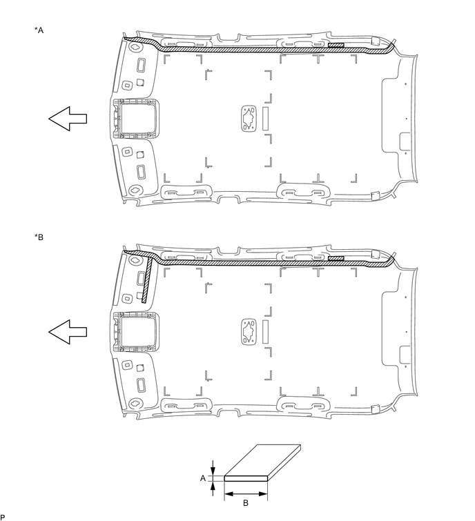
Text in Illustration *A w/o Digital Audio Broadcasting Antenna or Television Antenna Assembly *B w/ Digital Audio Broadcasting Antenna or Television Antenna Assembly 
Double-sided Tape 
Front
-
Remove the old double-sided tape from the roof headlining assembly.
-
Prepare the appropriate amount of new double-sided tape.
Tech Tips
Be careful not to touch the adhesive surface.
Area Dimension A 1.0 mm (0.0394 in.) B 15.0 mm (0.591 in.) -
Apply the double-sided tape to the roof headlining assembly while aligning the tape with the markings on the roof headlining assembly.
-
Peel off the release paper from the double-sided tape.
-
-
Install the No. 2 antenna cord sub-assembly to the roof headlining assembly from the front of the vehicle.
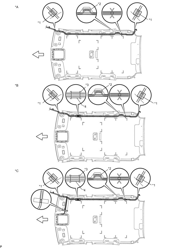
Text in Illustration *A w/o Telematics Transceiver *B w/ Telematics Transceiver *C w/ Digital Audio Broadcasting Antenna or Television Antenna Assembly - - *1 Protrusion *2 Adjustment Area *3 Marking *4 Antenna Protector 
Double-sided Tape Marking Tape 
Tape Front Tech Tips
Align the taped part of the antenna cable with the protrusion of the roof headlining assembly, and apply tape to secure the cable to the roof headlining assembly.
-
w/o Telematics Transceiver:
-
Put the strips of the tape back to the positions shown in the illustration in order to secure the antenna cord to the roof headlining assembly.
Tech Tips
-
If the tape is no longer sticky, use other tape, such as packing tape, that has enough adhesion to secure the antenna cord to the roof headlining assembly.
-
For the right front corner of the roof headlining assembly, align the marking tape on the antenna cord with the protrusion of the roof headlining assembly, and wrap tape around the antenna cord and roof headlining assembly once or twice to securely hold them.
-
For the right rear corner of the roof headlining assembly, align the marking tape on the antenna cord with the rear edge of the roof headlining assembly, and secure the antenna cord to the roof headlining assembly with tape.
-
If the entire length of the antenna cord does not fit, adjust the length by tucking in the cord at the area shown in the illustration.
-
-
-
w/ Telematics Transceiver or w/ Digital Audio Broadcasting Antenna or Television Antenna Assembly:
-
Put the strips of the tape back to the positions shown in the illustration in order to secure the antenna cord to the roof headlining assembly.
Tech Tips
-
If the tape is no longer sticky, use other tape, such as packing tape, that has enough adhesion to secure the antenna cord to the roof headlining assembly.
-
For the right front corner of the roof headlining assembly, align the marking tape on the antenna cord with the protrusion of the roof headlining, and wrap tape around the antenna cord and roof headlining assembly once or twice to securely hold them.
-
Align the markings on the roof headlining assembly with the antenna protector.
-
For the right rear corner of the roof headlining assembly, align the marking tape on the antenna cord with the rear edge of the roof headlining assembly, and secure the antenna cord to the roof headlining assembly with tape.
-
If the entire length of the antenna cord does not fit, adjust the length by tucking in the cord at the area shown in the illustration.
-
-
-
-
INSTALL ROOF HEADLINING ASSEMBLY
-
INSTALL ANTENNA CORD SUB-ASSEMBLY (for LHD)
-
Engage the 6 clamps.
-
Connect the connector.
-
Install the antenna cord sub-assembly with the bolt.
-
-
INSTALL UPPER INSTRUMENT PANEL ASSEMBLY (for LHD)
-
INSTALL ANTENNA CORD SUB-ASSEMBLY (for RHD)
-
Engage the 10 clamps.
-
Connect the connector.
-
Install the antenna cord sub-assembly with the bolt.
-
-
INSTALL LOWER INSTRUMENT PANEL SUB-ASSEMBLY (for RHD)