STEERING COLUMN ASSEMBLY INSTALLATION

CAUTION / NOTICE / HINT
Note
-
Do not replace the spiral cable with the auxiliary battery connected and the power switch on (IG).
-
Do not rotate the spiral cable without the steering wheel with the auxiliary battery connected and the power switch on (IG).
-
Ensure that the steering wheel is installed and aligned straight when inspecting the steering sensor.
-
Do not remove the steering sensor from the spiral cable.
PROCEDURE
-
INSPECT STEERING COLUMN ASSEMBLY
-
INSTALL NO. 2 STEERING INTERMEDIATE SHAFT ASSEMBLY
-
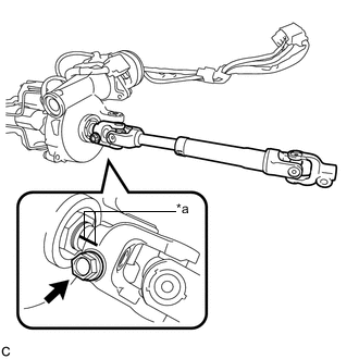
Text in Illustration *a Matchmark Align the matchmarks on the No. 2 steering intermediate shaft assembly and steering column assembly to install the No. 2 steering intermediate shaft assembly.
-
Install the bolt.
- Torque:
- 35 N*m { 357 kgf*cm, 26 ft.*lbf }
-
-
ALIGN FRONT WHEELS FACING STRAIGHT AHEAD
-
INSTALL STEERING POST ASSEMBLY (for LHD)
-
Install the steering post assembly with the bolt and 2 nuts.
- Torque:
- Bolt
- 36 N*m { 367 kgf*cm, 27 ft.*lbf }
- Nut
- 21 N*m { 214 kgf*cm, 15 ft.*lbf }
-
Engage the wire harness clamps to the steering post assembly.
-
Engage the 2 wire harness clamps.
-
Connect the connector to the power steering ECU assembly.
-
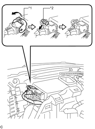
Text in Illustration *1 Lock Lever *2 Lock of Lock Lever Connect the connector to the power steering ECU assembly.
Tech Tips
As shown in the illustration, return the lock lever to its original position to connect the connector and securely push in the lock of the lock lever.
-
-
INSTALL STEERING POST ASSEMBLY (for RHD)
-
Install the steering post assembly with the bolt and 2 nuts.
- Torque:
- Bolt
- 36 N*m { 367 kgf*cm, 27 ft.*lbf }
- Nut
- 21 N*m { 214 kgf*cm, 15 ft.*lbf }
-
Engage the wire harness clamps to the steering post assembly.
-
Engage the 2 wire harness clamps.
-
-
CONNECT NO. 2 STEERING INTERMEDIATE SHAFT ASSEMBLY
-
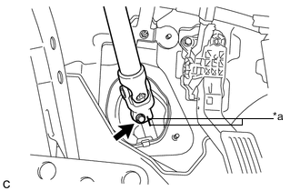
Text in Illustration *a Matchmark Align the matchmarks on the No. 2 steering intermediate shaft assembly and steering intermediate shaft to connect the No. 2 steering intermediate shaft assembly to the steering intermediate shaft.
-
Install the bolt.
- Torque:
- 35 N*m { 357 kgf*cm, 26 ft.*lbf }
-
-
INSTALL COLUMN HOLE COVER SILENCER SHEET
-
Install the column hole cover silencer sheet with the 2 clips.
-
Install the floor carpet.
-
-
INSTALL NO. 1 AIR DUCT SUB-ASSEMBLY (for LHD)
-
Engage the 2 claws to install the No. 1 air duct sub-assembly.
-
-
INSTALL STOP LIGHT SWITCH ASSEMBLY (for LHD)
-
INSTALL LOWER NO. 1 INSTRUMENT PANEL AIRBAG ASSEMBLY (for LHD)
-
INSTALL UPPER INSTRUMENT PANEL ASSEMBLY (for LHD)
-
INSTALL NO. 2 AIR DUCT SUB-ASSEMBLY (for RHD)
-
Engage the 2 claws to install the No. 2 air duct sub-assembly.
-
-
INSTALL BRAKE PEDAL SUPPORT ASSEMBLY (for RHD)
-
INSTALL TURN SIGNAL SWITCH ASSEMBLY WITH SPIRAL CABLE SUB-ASSEMBLY
Note
-
Do not replace the spiral cable with the auxiliary battery connected and the power switch on (IG).
-
Do not rotate the spiral cable without the steering wheel with the auxiliary battery connected and the power switch on (IG).
-
Ensure that the steering wheel is installed and aligned straight when inspecting the steering sensor.
-
Do not remove the steering sensor from the spiral cable.
-
Using pliers, expand the clamp.
-
While holding the clamp expanded, install the turn signal switch assembly with spiral cable sub-assembly to the steering post assembly and engage the claw.
-
Return the clamp to its original position.
-
Connect the connectors to the turn signal switch assembly with spiral cable sub-assembly.
-
-
INSTALL STEERING COLUMN COVER
Note
If the steering column cover is installed in the incorrect order, it will not be possible to assemble the steering column cover.
-
Engage the 2 claws to install the steering column cover (upper side).
-
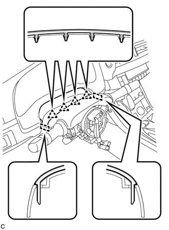
Engage the 4 clips and 2 guides to the steering column cover (upper side).
-
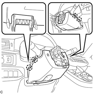
Engage the 4 claws to install the steering column cover (lower side).
-
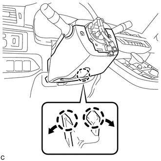
Engage the 2 claws.
Tech Tips
Spread the claws and press the area around the claws to engage them.
-
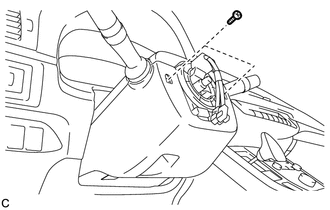
Install the 2 screws.
- Torque:
- 2.0 N*m { 20 kgf*cm, 18 in.*lbf }
-
-
ALIGN FRONT WHEELS FACING STRAIGHT AHEAD
-
ADJUST SPIRAL CABLE WITH SENSOR SUB-ASSEMBLY
-
INSTALL STEERING WHEEL ASSEMBLY
-
CHECK STEERING WHEEL CENTER POINT
-
INSTALL HORN BUTTON ASSEMBLY
-
ROTATION ANGLE SENSOR VALUE INITIALIZATION AND TORQUE SENSOR ZERO POINT CALIBRATION