BRAKE BOOSTER(for RHD) REMOVAL
PROCEDURE
-
PRECAUTION
Note
After turning the power switch off, waiting time may be required before disconnecting the cable from the negative (-) auxiliary battery terminal, Therefore, make sure to read the disconnecting the cable from the negative (-) auxiliary battery terminal notices before proceeding with work Click here.
-
DISABLE BRAKE CONTROL
-
REMOVE WINDSHIELD WIPER MOTOR AND LINK ASSEMBLY
-
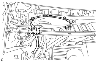
REMOVE NO. 1 HEATER AIR DUCT SPLASH SHIELD SEAL
-
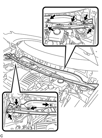
Disengage the 2 claws and remove the No. 1 heater air duct splash shield seal.
-
-
REMOVE NO. 2 HEATER AIR DUCT SPLASH SHIELD SEAL
-
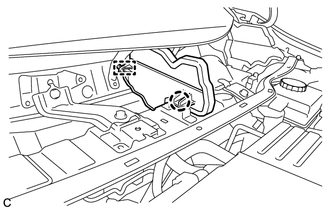
Disengage the claw and guide, and remove the No. 2 heater air duct splash shield seal.
-
-
REMOVE COWL BODY MOUNTING REINFORCEMENT RH
-
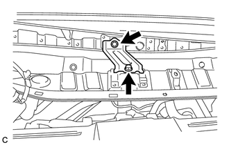
Remove the 2 bolts and cowl body mounting reinforcement RH.
-
-
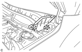
REMOVE OUTER COWL TOP PANEL SUB-ASSEMBLY
-
Disengage the clamp and separate the wire harness.
-
w/ Wiper Deicer:
Disengage the 3 clamps, disconnect the connector and separate the wire harness.
-
Remove the 9 bolts and outer cowl top panel sub-assembly.
-
-
REMOVE SUSPENSION TOWER DAMPER (w/ Suspension Tower Damper)
-
DRAIN BRAKE FLUID
Note
If brake fluid leaks onto any painted surface, immediately clean it off.
-
REMOVE NO. 1 INSTRUMENT PANEL UNDER COVER SUB-ASSEMBLY
-
REMOVE BRAKE PEDAL RETURN SPRING
-
REMOVE PUSH ROD PIN
-
SEPARATE RESERVOIR TUBE ASSEMBLY
-
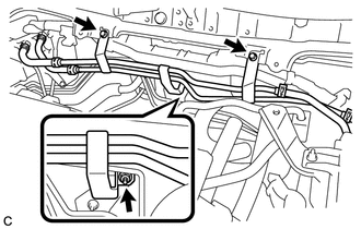
Remove the 2 bolts, nut and separate the reservoir tube assembly.
-
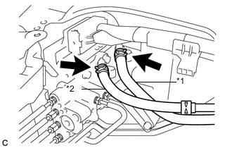
Text in Illustration *1 No. 1 Reservoir Hose *2 No. 2 Reservoir Hose Move the 2 clips and disconnect the No. 1 reservoir hose and No. 2 reservoir hose.
-
-
REMOVE BRAKE BOOSTER WITH MASTER CYLINDER ASSEMBLY
-
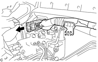
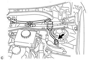
Disengage the clamp.
-
Release the lock lever and disconnect the connector from the brake booster with master cylinder assembly.
Note
Be careful not to allow the brake fluid to enter the removed connector.
-
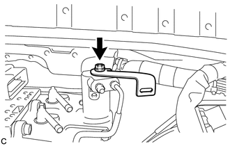
Remove the bolt and wire harness clamp bracket.
-
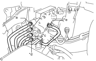
Using a union nut wrench, disconnect the 5 brake lines from the brake booster with master cylinder assembly.
-
Use tags or make a memo to identify the places to reconnect.
Text in Illustration *a to Front Wheel Cylinder LH *b to Rear Wheel Cylinder RH *c to Brake Booster Pump Assembly *d to Rear Wheel Cylinder LH *e to Front Wheel Cylinder RH -
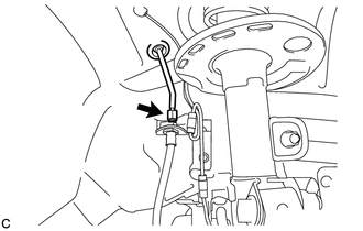
Using a union nut wrench, disconnect the brake line from the front flexible hose RH.
-
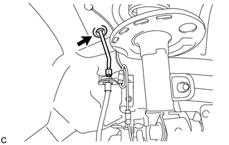
Disengage the grommet and separate the brake line.
-
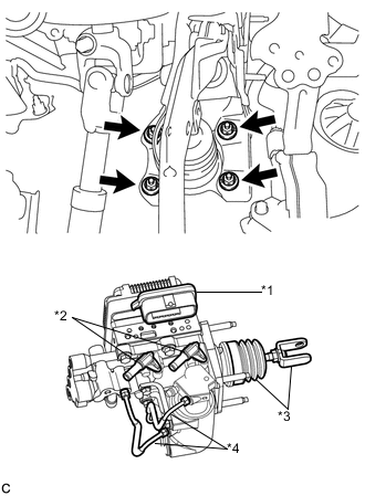
Text in Illustration *1 Connector Portion *2 Union *3 Push Rod Clevis and Boot *4 Front No. 2 Brake Tube Remove the 4 nuts and brake booster with master cylinder assembly.
Note
-
Do not kink or damage the brake lines.
-
Do not carry the brake booster with master cylinder assembly by the portion shown in bold in the illustration.
-
-
-
REMOVE BRAKE BOOSTER GASKET