REAR DOOR SUNSHADE SYSTEM TERMINALS OF ECU
-
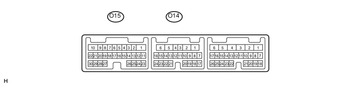
CHECK REAR DOOR ECU LH
-
Disconnect the O14 ECU connector.
-
Measure the voltage and resistance of the wire harness side connector.
Terminal No.
(Symbols)
Wiring Color Terminal Description Condition Specified Condition O14-1 (GND) - Body ground W-B - Body ground Ground Always Below 1 Ω O14-6 (BDR) - O14-1 (GND) L - W-B Battery power supply Always 11 to 14 V O14-11 (CPUB) - O14-1 (GND) R - W-B Battery power supply Always 11 to 14 V If the result is not as specified, there may be a malfunction on the wire harness side.
-
Reconnect the O14 ECU connectors.
-
Measure the voltage of the connector.
Terminal No.
(Symbols)
Wiring Color Terminal Description Condition Specified Condition O15-1 (SSA+) - O14-1 (GND) B - W-B Door sunshade motor output (Raise) Door sunshade is raising 11 to 14 V Except above condition Below 1 V O15-8 (SHSB) - O14-1 (GND) B - W-B Hall sensor power supply ECU wake-up state 11 to 14 V Except above condition Below 1 V O15-10 (SSA-) - O14-1 (GND) L - W-B Door sunshade motor output (Lower) Door sunshade is lowering 11 to 14 V Except above condition Below 1 V O15-27 (SHS1) - O14-1 (GND) L - W-B Hall sensor 1 input Engine switch on (IG), door sunshade is raising or lowering Pulse generation Except above condition Below 1 V or 11 to 14 V O15-28 (SHS2) - O14-1 (GND) R - W-B Hall sensor 2 input Engine switch on (IG), door sunshade is raising or lowering Pulse generation Except above condition Below 1 V or 11 to 14 V O15-30 (SHSE) - O14-1 (GND) Y - W-B Ground Always Below 1 Ω
-
If the result is not as specified, the ECU or door sunshade may have a malfunction.
-
-
-
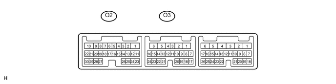
CHECK REAR DOOR ECU RH
-
Disconnect the O3 ECU connector.
-
Measure the voltage and resistance of the wire harness side connector.
Terminal No.
(Symbols)
Wiring Color Terminal Description Condition Specified Condition O3-1 (GND) - Body ground W-B - Body ground Ground Always Below 1 Ω O3-6 (BDR) - O3-1 (GND) L - W-B Battery power supply Always 11 to 14 V O3-11 (CPUB) - O3-1 (GND) R - W-B Battery power supply Always 11 to 14 V
-
If the result is not as specified, there may be a malfunction on the wire harness side.
-
-
Reconnect the O3 ECU connectors.
-
Measure the voltage of the connector.
Terminal No.
(Symbols)
Wiring Color Terminal Description Condition Specified Condition O2-1 (SSA+) - O3-1 (GND) B - W-B Door sunshade motor output (Raise) Door sunshade is raising 11 to 14 V Except above condition Below 1 V O2-10 (SSA-) - O3-1 (GND) L - W-B Door sunshade motor output (Lower) Door sunshade is lowering 11 to 14 V ECU wake-up state 11 to 14 V Except above condition Below 1 V Except above condition Below 1 V O2-27 (SHS1) - O3-1 (GND) L - W-B Hall sensor 1 input Engine switch on (IG), door sunshade is raising or lowering Pulse generation Except above condition Below 1 V or 11 to 14 V O2-28 (SHS2) - O3-1 (GND) R - W-B Hall sensor 2 input Engine switch on (IG), door sunshade is raising or lowering Pulse generation Except above condition Below 1 V or 11 to 14 V O2-30 (SHSE) - O3-1 (GND) Y - W-B Ground Always Below 1 Ω
-
If the result is not as specified, the ECU or door sunshade may have a malfunction.
-
-