SEAT HEATER SYSTEM TERMINALS OF ECU
-
CHECK SEAT CLIMATE CONTROL ECU LH
-
Disconnect the f13 ECU connector.
-
Measure the voltage and resistance of the wire harness side connectors.
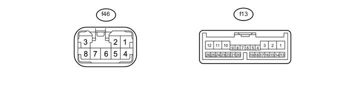
Terminal No. (Symbols) Wiring Color Terminal Description Condition Specified Condition f13-1 (IG) - Body ground Y - Body ground Power source Engine switch on (IG) 11 to 14 V f13-2 (SYSB) - Body ground V - Body ground Power source Always 11 to 14 V f13-12 (GND) - Body ground W-B - Body ground Ground Always Below 1 Ω f13-13 (LIN) - Body ground V - Body ground LIN line Always 10 kΩ or higher If the result is not as specified, there may be a malfunction on the wire harness side.
-
Reconnect the f13 connector.
-
Measure the voltage of the connectors.
Terminal No. (Symbols) Wiring Color Terminal Description Condition Specified Condition f46-1 (AMP) - Body ground L - Body ground Power supply for seat heater Engine switch on (IG)
Seat heater switch OFF
Below 1 V Engine switch on (IG)
Turn seat heater switch Max. WARM
11 to 14 V f46-6 (H5) - Body ground BR - Body ground Seat heater temp. signal Engine switch off Below 1 V Engine switch on (IG) 1 to 4 V f46-7 (HS) - Body ground P - Body ground Seat heater temp. signal ground Always Below 1 V
-
If the result is not as specified, the ECU may have a malfunction.
-
-
-
CHECK SEAT CLIMATE CONTROL ECU RH

-
Disconnect the f8 ECU connector.
-
Measure the voltage and resistance of the wire harness side connectors.
Terminal No. (Symbols) Wiring Color Terminal Description Condition Specified Condition f8-1 (IG) - Body ground Y - Body ground Power source Engine switch on (IG) 11 to 14 V f8-2 (SYSB) - Body ground G - Body ground Power source Always 11 to 14 V f8-11 (VER) - Body ground W-B - Body ground Ground Always Below 1 Ω f8-12 (GND) - Body ground W-B - Body ground Ground Always Below 1 Ω f8-13 (LIN) - Body ground V - Body ground LIN line Always 10 kΩ or higher If the result is not as specified, there may be a malfunction on the wire harness side.
-
Reconnect the f8 ECU connector.
-
Measure the voltage of the connectors.
Terminal No. (Symbols) Wiring Color Terminal Description Condition Specified Condition f45-1 (AMP) - Body ground L - Body ground Power supply for seat heater Engine switch on (IG)
Seat heater switch OFF
Below 1 V Engine switch on (IG)
Turn seat heater switch Max. WARM
11 to 14 V f45-6 (H5) - Body ground BR - Body ground Seat heater temp. signal Engine switch off Below 1 V Engine switch on (IG) 1 to 4 V f45-7 (HS) - Body ground P - Body ground Seat heater temp. signal ground Always Below 1 V
-
If the result is not as specified, the ECU may have a malfunction.
-
-