FRONT POWER SEAT CONTROL SYSTEM, Diagnostic DTC:B2658
| DTC Code | DTC Name |
|---|---|
| B2658 | Short in Sensor with Motor Power Supply Circuit |
DESCRIPTION
This DTC is stored when a power seat motor operates (a position control sensor is being supplied with power) and the power supply voltage does not rise to the specified value.
| DTC Code | DTC Detection Condition | Trouble Area |
|---|---|---|
| B2658 | A problem with the voltage supplied to the position control sensor. |
|
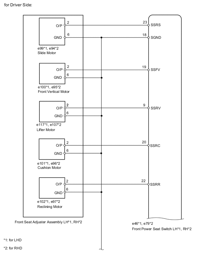
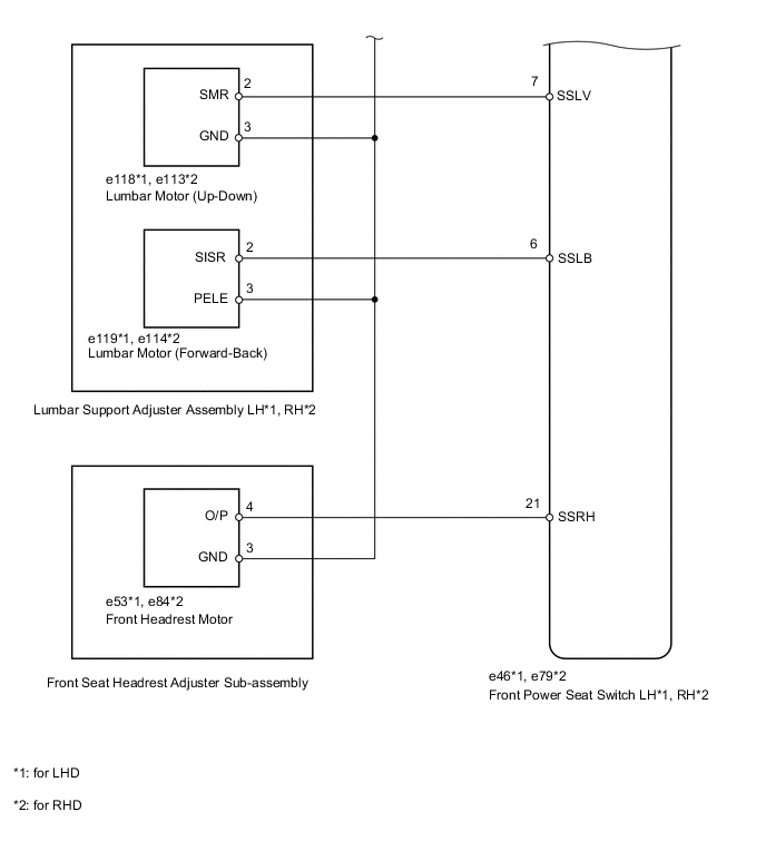
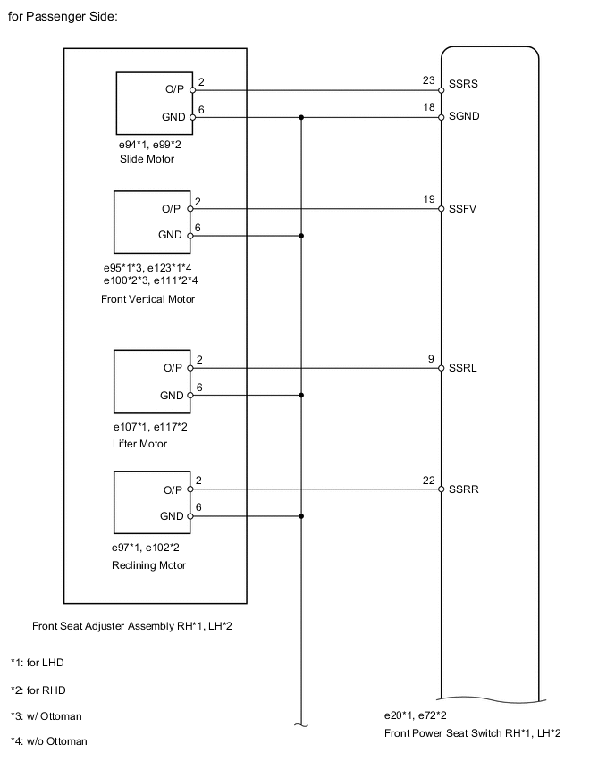
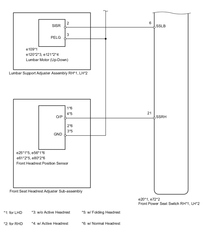
WIRING DIAGRAM
PROCEDURE
-
CHECK FOR DTC
-
Clear the DTC Click here.
-
Using the intelligent tester, determine the area that output the DTC.
Result Result Proceed to B2658 output from driver seat ECU A B2658 output from passenger seat ECU B B2658 is not output. C
-
B 
CHECK HARNESS AND CONNECTOR (FRONT POWER SEAT SWITCH - POWER SEAT MOTOR) Click here
C 
USE SIMULATION METHOD TO CHECK Click here
A 
-
-
CHECK HARNESS AND CONNECTOR (FRONT POWER SEAT SWITCH - POWER SEAT MOTOR)

-
for LHD:
-
Disconnect the e46 switch connector.
-
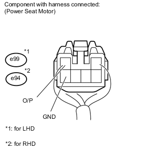
Disconnect the e99 motor connector.
-
-
for RHD:
-
Disconnect the e79 switch connector.
-
Disconnect the e94 motor connector.
-
-
Disconnect the e63 motor connector.
-
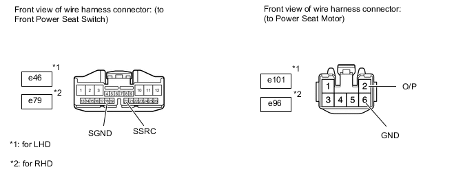
Measure the resistance according to the value(s) in the table below.
Standard resistance for LHD Tester Connection Condition Specified Condition e46-23 (SSRS) - e99-2 (O/P) Always Below 1 Ω e46-18 (SGND) - e99-6 (GND) Always Below 1 Ω e46-23 (SSRS) - e46-18 (SGND) Always 10 kΩ or higher e46-23 (SSRS) - Body ground Always 10 kΩ or higher e46-18 (SGND) - Body ground Always 10 kΩ or higher for RHD Tester Connection Condition Specified Condition e79-23 (SSRS) - e99-2 (O/P) Always Below 1 Ω e79-18 (SGND) - e94-6 (GND) Always Below 1 Ω e79-23 (SSRS) - e94-18 (SGND) Always 10 kΩ or higher e79-23 (SSRS) - Body ground Always 10 kΩ or higher e79-18 (SGND) - Body ground Always 10 kΩ or higher
NG
REPAIR OR REPLACE HARNESS OR CONNECTOR
OK
-
-
CHECK FRONT POWER SEAT SWITCH (POSITION CONTROL SENSOR)
-
Measure the voltage according to the value(s) in the table below.
Standard voltage for LHD Tester Connection Switch Condition Specified Condition e99-2 (O/P) - e99-6 (GND) Sliding switch ON 0 to 8 V for RHD Tester Connection Switch Condition Specified Condition e94-2 (O/P) - e94-6 (GND) Sliding switch ON 0 to 8 V
NG
REPLACE FRONT POWER SEAT SWITCH Click here
OK
-
-
CHECK HARNESS AND CONNECTOR (FRONT POWER SEAT SWITCH - POWER SEAT MOTOR)
-
for LHD:
-
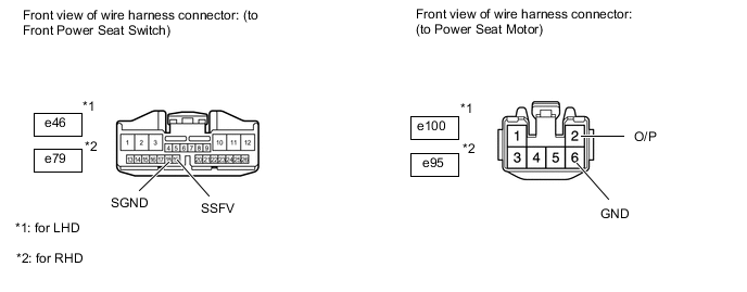
Disconnect the e46 switch connector.
-
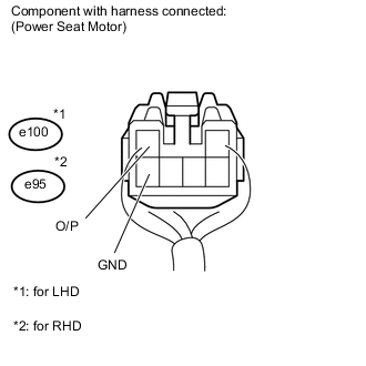
Disconnect the e100 motor connector.
-
-
for RHD:
-
Disconnect the e79 switch connector.
-
Disconnect the e95 motor connector.
-
-
Measure the resistance according to the value(s) in the table below.
Standard resistance for LHD Tester Connection Condition Specified Condition e46-19 (SSFV) - e100-2 (O/P) Always Below 1 Ω e46-18 (SGND) - e100-6 (GND) Always Below 1 Ω e46-19 (SSFV) - e46-18 (SGND) Always 10 kΩ or higher e46-19 (SSFV) - Body ground Always 10 kΩ or higher e46-18 (SGND) - Body ground Always 10 kΩ or higher for RHD Tester Connection Condition Specified Condition e79-19 (SSFV) - e95-2 (O/P) Always Below 1 Ω e79-18 (SGND) - e95-6 (GND) Always Below 1 Ω e79-19 (SSFV) - e79-18 (SGND) Always 10 kΩ or higher e79-19 (SSFV) - Body ground Always 10 kΩ or higher e79-18 (SGND) - Body ground Always 10 kΩ or higher
NG
REPAIR OR REPLACE HARNESS OR CONNECTOR
OK
-
-
CHECK FRONT POWER SEAT SWITCH (POSITION CONTROL SENSOR)
-
Measure the voltage according to the value(s) in the table below.
Standard voltage for LHD Tester Connection Switch Condition Specified Condition e100-2 (O/P) - e100-6 (GND) Front vertical switch ON 0 to 8 V for RHD Tester Connection Switch Condition Specified Condition e95-2 (O/P) - e95-6 (GND) Front vertical switch ON 0 to 8 V
NG
REPLACE FRONT POWER SEAT SWITCH Click here
OK
-
-
CHECK HARNESS AND CONNECTOR (FRONT POWER SEAT SWITCH - POWER SEAT MOTOR)
-
for LHD:
-
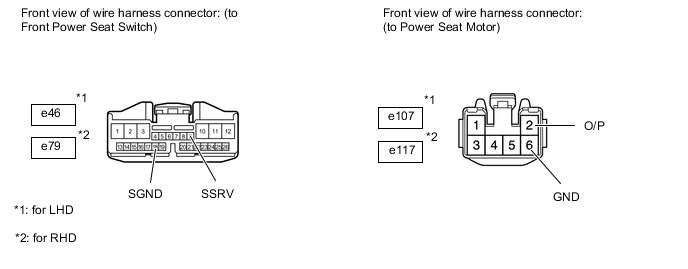
Disconnect the e46 switch connector.
-
Disconnect the e117 motor connector.
-
-
for RHD:
-
Disconnect the e79 switch connector.
-
Disconnect the e107 motor connector.
-
-
Measure the resistance according to the value(s) in the table below.
Standard resistance for LHD Tester Connection Condition Specified Condition e46-9 (SSRV) - e117-2 (O/P) Always Below 1 Ω e46-18 (SGND) - e117-6 (GND) Always Below 1 Ω e46-9 (SSRV) - e46-18 (SGND) Always 10 kΩ or higher e46-9 (SSRV) - Body ground Always 10 kΩ or higher e46-18 (SGND) - Body ground Always 10 kΩ or higher for RHD Tester Connection Condition Specified Condition e79-9 (SSRV) - e107-2 (O/P) Always Below 1 Ω e79-18 (SGND) - e107-6 (GND) Always Below 1 Ω e79-9 (SSRV) - e79-18 (SGND) Always 10 kΩ or higher e79-9 (SSRV) - Body ground Always 10 kΩ or higher e79-18 (SGND) - Body ground Always 10 kΩ or higher
NG
REPAIR OR REPLACE HARNESS OR CONNECTOR
OK
-
-
CHECK FRONT POWER SEAT SWITCH (POSITION CONTROL SENSOR)
-
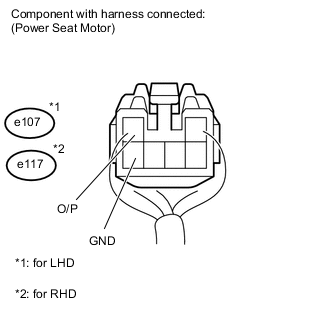
Measure the voltage according to the value(s) in the table below.
Standard voltage for LHD Tester Connection Switch Condition Specified Condition e117-2 (O/P) - e117-6 (GND) Lifter switch ON 0 to 8 V for RHD Tester Connection Switch Condition Specified Condition e107-2 (O/P) - e107-6 (GND) Lifter switch ON 0 to 8 V
NG
REPLACE FRONT POWER SEAT SWITCH Click here
OK
-
-
CHECK HARNESS AND CONNECTOR (FRONT POWER SEAT SWITCH - POWER SEAT MOTOR)
-
for LHD:
-
Disconnect the e46 switch connector.
-
Disconnect the e101 motor connector.
-
-
for RHD:
-
Disconnect the e79 switch connector.
-
Disconnect the e96 motor connector.
-
-
Measure the resistance according to the value(s) in the table below.
Standard resistance for LHD Tester Connection Condition Specified Condition e46-20 (SSRC) - e101-2 (O/P) Always Below 1 Ω e46-18 (SGND) - e101-6 (GND) Always Below 1 Ω e46-20 (SSRC) - e46-18 (SGND) Always 10 kΩ or higher e46-20 (SSRC) - Body ground Always 10 kΩ or higher e46-18 (SGND) - Body ground Always 10 kΩ or higher for RHD Tester Connection Condition Specified Condition e79-20 (SSRC) - e96-2 (O/P) Always Below 1 Ω e79-18 (SGND) - e96-6 (GND) Always Below 1 Ω e79-20 (SSRC) - e79-18 (SGND) Always 10 kΩ or higher e79-20 (SSRC) - Body ground Always 10 kΩ or higher e79-18 (SGND) - Body ground Always 10 kΩ or higher
NG
REPAIR OR REPLACE HARNESS OR CONNECTOR
OK
-
-
CHECK FRONT POWER SEAT SWITCH (POSITION CONTROL SENSOR)
-
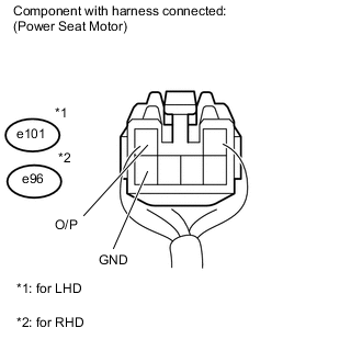
Measure the voltage according to the value(s) in the table below.
Standard voltage for LHD Tester Connection Switch Condition Specified Condition e101-2 (O/P) - e101-6 (GND) Cushion switch ON 0 to 8 V for RHD Tester Connection Switch Condition Specified Condition e96-2 (O/P) - e96-6 (GND) Cushion switch ON 0 to 8 V
NG
REPLACE FRONT POWER SEAT SWITCH Click here
OK
-
-
CHECK HARNESS AND CONNECTOR (FRONT POWER SEAT SWITCH - POWER SEAT MOTOR)
-
for LHD:

-
Disconnect the e46 switch connector.
-
Disconnect the e102 motor connector.
-
-
for RHD:
-
Disconnect the e79 switch connector.
-
Disconnect the e97 motor connector.
-
-
Measure the resistance according to the value(s) in the table below.
Standard resistance for LHD Tester Connection Condition Specified Condition e46-22 (SSRR) - e102-2 (O/P) Always Below 1 Ω e46-18 (SGND) - e102-6 (GND) Always Below 1 Ω e46-22 (SSRR) - e46-18 (SGND) Always 10 kΩ or higher e46-22 (SSRR) - Body ground Always 10 kΩ or higher e46-18 (SGND) - Body ground Always 10 kΩ or higher for RHD Tester Connection Condition Specified Condition e79-22 (SSRR) - e97-2 (O/P) Always Below 1 Ω e79-18 (SGND) - e97-6 (GND) Always Below 1 Ω e79-22 (SSRR) - e46-18 (SGND) Always 10 kΩ or higher e79-22 (SSRR) - Body ground Always 10 kΩ or higher e79-18 (SGND) - Body ground Always 10 kΩ or higher
NG
REPAIR OR REPLACE HARNESS OR CONNECTOR
OK
-
-
CHECK FRONT POWER SEAT SWITCH (POSITION CONTROL SENSOR)
-
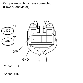
Measure the voltage according to the value(s) in the table below.
Standard voltage for LHD Tester Connection Switch Condition Specified Condition e102-2 (O/P) - e102-6 (GND) Reclining switch ON 0 to 8 V for RHD Tester Connection Switch Condition Specified Condition e97-2 (O/P) - e97-6 (GND) Reclining switch ON 0 to 8 V
NG
REPLACE FRONT POWER SEAT SWITCH Click here
OK
-
-
CHECK FRONT SEAT ADJUSTER ASSEMBLY
-
Temporarily replace the front seat adjuster assembly with a new or normally functioning one Click here.
-
Clear the DTC Click here.
-
Recheck the DTC Click here.
OK DTC B2658 is not output.
OK
END (FRONT SEAT ADJUSTER ASSEMBLY WAS DEFECTIVE)
NG
-
-
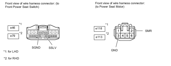
CHECK HARNESS AND CONNECTOR (FRONT POWER SEAT SWITCH - POWER SEAT MOTOR)
-
for LHD:
-
Disconnect the e46 switch connector.
-
Disconnect the e118 motor connector.
-
-
for RHD:
-
Disconnect the e79 switch connector.
-
Disconnect the e113 motor connector.
-
-
Measure the resistance according to the value(s) in the table below.
Standard resistance for LHD Tester Connection Condition Specified Condition e46-7 (SSLV) - e118-2 (SMR) Always Below 1 Ω e46-18 (SGND) - e118-3 (GND) Always Below 1 Ω e46-7 (SSLV) - e46-18 (SGND) Always 10 kΩ or higher e46-7 (SSLV) - Body ground Always 10 kΩ or higher e46-18 (SGND) - Body ground Always 10 kΩ or higher for RHD Tester Connection Condition Specified Condition e79-7 (SSLV) - e113-2 (SMR) Always Below 1 Ω e79-18 (SGND) - e113-3 (GND) Always Below 1 Ω e79-7 (SSLV) - e79-18 (SGND) Always 10 kΩ or higher e79-7 (SSLV) - Body ground Always 10 kΩ or higher e79-18 (SGND) - Body ground Always 10 kΩ or higher
NG
REPAIR OR REPLACE HARNESS OR CONNECTOR
OK
-
-
CHECK FRONT POWER SEAT SWITCH (POSITION CONTROL SENSOR)
-
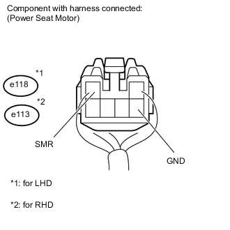
Measure the voltage according to the value(s) in the table below.
Standard voltage for LHD Tester Connection Switch Condition Specified Condition e118-2 (SMR) - e118-3 (GND) Lumbar switch (Up-Down) ON 0 to 8 V for RHD Tester Connection Switch Condition Specified Condition e113-2 (SMR) - e113-3 (GND) Lumbar switch (Up-Down) ON 0 to 8 V
NG
REPLACE FRONT POWER SEAT SWITCH Click here
OK
-
-
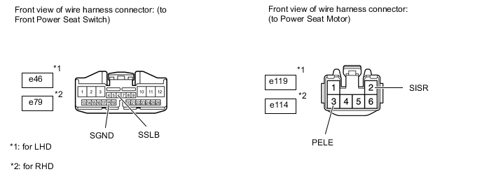
CHECK HARNESS AND CONNECTOR (FRONT POWER SEAT SWITCH - POWER SEAT MOTOR)
-
for LHD:
-
Disconnect the e46 switch connector.
-
Disconnect the e119 motor connector.
-
-
for RHD:
-
Disconnect the e79 switch connector.
-
Disconnect the e114 motor connector.
-
-
Measure the resistance according to the value(s) in the table below.
Standard resistance for LHD Tester Connection Condition Specified Condition e46-6 (SSLB) - e119-2 (SISR) Always Below 1 Ω e46-18 (SGND) - e119-3 (PELE) Always Below 1 Ω e46-6 (SSLB) - e46-18 (SGND) Always 10 kΩ or higher e46-6 (SSLB) - Body ground Always 10 kΩ or higher e46-18 (SGND) - Body ground Always 10 kΩ or higher for RHD Tester Connection Condition Specified Condition e79-6 (SSLB) - e114-2 (SISR) Always Below 1 Ω e79-18 (SGND) - e114-3 (PELE) Always Below 1 Ω e79-6 (SSLB) - e79-18 (SGND) Always 10 kΩ or higher e79-6 (SSLB) - Body ground Always 10 kΩ or higher e79-18 (SGND) - Body ground Always 10 kΩ or higher
NG
REPAIR OR REPLACE HARNESS OR CONNECTOR
OK
-
-
CHECK FRONT POWER SEAT SWITCH (POSITION CONTROL SENSOR)
-
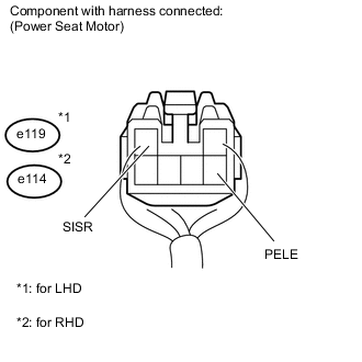
Measure the voltage according to the value(s) in the table below.
Standard voltage for LHD Tester Connection Switch Condition Specified Condition e119-2 (SISR) - e119-3 (PELE) Lumbar switch (Forward-Back) ON 0 to 8 V for RHD Tester Connection Switch Condition Specified Condition e114-2 (SISR) - e114-3 (PELE) Lumbar switch (Forward-Back) ON 0 to 8 V
NG
REPLACE FRONT POWER SEAT SWITCH Click here
OK
-
-
CHECK LUMBAR SUPPORT ADJUSTER ASSEMBLY
-
Temporarily replace the lumbar support adjuster assembly LH with a new or normally functioning one Click here.
-
Clear the DTC Click here.
-
Recheck the DTC Click here.
OK DTC B2658 is not output.
OK
END (LUMBAR SUPPORT ADJUSTER ASSEMBLY WAS DEFECTIVE)
NG
-
-
CHECK HARNESS AND CONNECTOR (FRONT POWER SEAT SWITCH - POWER SEAT MOTOR)
-
for LHD:
-
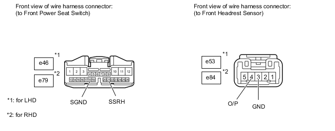
Disconnect the e46 switch connector.
-
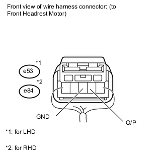
Disconnect the e53 motor connector.
-
-
for RHD:
-
Disconnect the e79 switch connector.
-
Disconnect the e84 motor connector.
-
-
Measure the resistance according to the value(s) in the table below.
Standard resistance for LHD Tester Connection Condition Specified Condition e46-21 (SSRH) - e53-4 (O/P) Always Below 1 Ω e46-18 (SGND) - e53-3 (GND) Always Below 1 Ω e46-21 (SSRH) - e46-18 (SGND) Always 10 kΩ or higher e46-21 (SSRH) - Body ground Always 10 kΩ or higher e46-18 (SGND) - Body ground Always 10 kΩ or higher for RHD Tester Connection Condition Specified Condition e79-21 (SSRH) - e84-4 (O/P) Always Below 1 Ω e79-18 (SGND) - e84-3 (GND) Always Below 1 Ω e79-21 (SSRH) - e79-18 (SGND) Always 10 kΩ or higher e79-21 (SSRH) - Body ground Always 10 kΩ or higher e79-18 (SGND) - Body ground Always 10 kΩ or higher
NG
REPAIR OR REPLACE HARNESS OR CONNECTOR
OK
-
-
CHECK FRONT POWER SEAT SWITCH LH (POSITION CONTROL SENSOR)
-
Measure the voltage according to the value(s) in the table below.
Standard voltage for LHD Tester Connection Switch Condition Specified Condition e53-4 (O/P) - e53-3 (GND) Headrest switch ON 0 to 8 V for RHD Tester Connection Switch Condition Specified Condition e84-4 (O/P) - e84-3 (GND) Headrest switch ON 0 to 8 V
NG
REPLACE FRONT POWER SEAT SWITCH Click here
OK
-
-
CHECK FRONT SEAT HEADREST ADJUSTER SUB-ASSEMBLY
-
Temporarily replace the front seat headrest sub-assembly with a new or normally functioning one Click here.
-
Clear the DTC Click here.
-
Recheck the DTC Click here.
OK DTC B2658 is not output.
OK
END (FRONT SEAT HEADREST ADJUSTER SUB-ASSEMBLY WAS DEFECTIVE)
NG
REPLACE FRONT POWER SEAT SWITCH Click here
-
-
CHECK HARNESS AND CONNECTOR (FRONT POWER SEAT SWITCH - POWER SEAT MOTOR)

-
for LHD:
-
Disconnect the e20 switch connector.
-
Disconnect the e94 motor connector.
-
-
for RHD:
-
Disconnect the e72 switch connector.
-
Disconnect the e99 motor connector.
-
-
Measure the resistance according to the value(s) in the table below.
Standard resistance for LHD Tester Connection Condition Specified Condition e20-23 (SSRS) - e94-2 (O/P) Always Below 1 Ω e20-18 (SGND) - e94-6 (GND) Always Below 1 Ω e20-23 (SSRS) - e20-18 (SGND) Always 10 kΩ or higher e20-23 (SSRS) - Body ground Always 10 kΩ or higher e20-18 (SGND) - Body ground Always 10 kΩ or higher for RHD Tester Connection Condition Specified Condition e72-23 (SSRS) - e99-2 (O/P) Always Below 1 Ω e72-18 (SGND) - e99-6 (GND) Always Below 1 Ω e72-23 (SSRS) - e72-18 (SGND) Always 10 kΩ or higher e72-23 (SSRS) - Body ground Always 10 kΩ or higher e72-18 (SGND) - Body ground Always 10 kΩ or higher
NG
REPAIR OR REPLACE HARNESS OR CONNECTOR
OK
-
-
CHECK FRONT POWER SEAT SWITCH RH (POSITION CONTROL SENSOR)
-

Measure the voltage according to the value(s) in the table below.
Standard voltage for LHD Tester Connection Switch Condition Specified Condition e94-2 (O/P) - e94-6 (GND) Sliding switch ON 0 to 8 V for RHD Tester Connection Switch Condition Specified Condition e99-2 (O/P) - e99-6 (GND) Sliding switch ON 0 to 8 V
NG
REPLACE FRONT SEAT POWER SWITCH Click here
OK
-
-
CHECK HARNESS AND CONNECTOR (FRONT POWER SEAT SWITCH - POWER SEAT MOTOR)
-
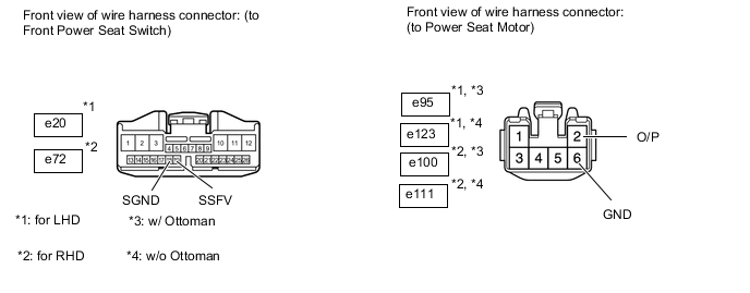
*1: w/ Ottoman
-
*2: w/o Ottoman
-
for LHD:
-
Disconnect the e20 switch connector.
-
Disconnect the e95*1 or e123*2 motor connector.
-
-
for RHD:
-
Disconnect the e72 switch connector.
-
Disconnect the e100*1 or e111*2 motor connector.
-
-
Measure the resistance according to the value(s) in the table below.
Standard resistance for LHD Tester Connection Condition Specified Condition e20-19 (SSFV) - e95-2 (O/P)*1 Always Below 1 Ω e20-19 (SSFV) - e123-2 (O/P)*2 Always Below 1 Ω e20-18 (SGND) - e95-6 (GND)*1 Always Below 1 Ω e20-18 (SGND) - e123-6 (GND)*2 Always Below 1 Ω e20-19 (SSFV) - e20-18 (SGND) Always 10 kΩ or higher e20-19 (SSFV) - Body ground Always 10 kΩ or higher e20-18 (SGND) - Body ground Always 10 kΩ or higher for LHD Tester Connection Condition Specified Condition e72-19 (SSFV) - e100-2 (O/P)*1 Always Below 1 Ω e72-19 (SSFV) - e111-2 (O/P)*2 Always Below 1 Ω e72-18 (SGND) - e100-6 (GND)*1 Always Below 1 Ω e72-18 (SGND) - e111-6 (GND)*2 Always Below 1 Ω e72-19 (SSFV) - e72-18 (SGND) Always 10 kΩ or higher e72-19 (SSFV) - Body ground Always 10 kΩ or higher e72-18 (SGND) - Body ground Always 10 kΩ or higher
NG
REPAIR OR REPLACE HARNESS OR CONNECTOR
OK
-
-
CHECK FRONT POWER SEAT SWITCH (POSITION CONTROL SENSOR)
-
*1: w/ Ottoman
-
*2: w/o Ottoman
-
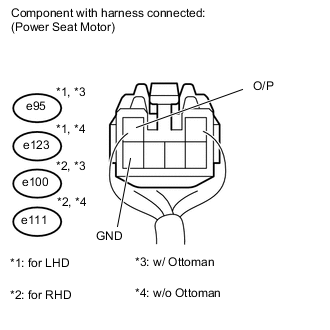
Measure the voltage according to the value(s) in the table below.
Standard voltage for LHD Tester Connection Switch Condition Specified Condition e95-2 (O/P) - e95-6 (GND)*1 Front vertical switch ON 0 to 8 V e123-2 (O/P) - e123-6 (GND)*2 Front vertical switch ON 0 to 8 V for RHD Tester Connection Switch Condition Specified Condition e100-2 (O/P) - e100-6 (GND)*1 Front vertical switch ON 0 to 8 V e111-2 (O/P) - e111-6 (GND)*2 Front vertical switch ON 0 to 8 V
NG
REPLACE FRONT SEAT POWER SWITCH Click here
OK
-
-
CHECK HARNESS AND CONNECTOR (FRONT POWER SEAT SWITCH - POWER SEAT MOTOR)

-
for LHD:
-
Disconnect the e20 switch connector.
-
Disconnect the e107 motor connector.
-
-
for RHD:
-
Disconnect the e72 switch connector.
-
Disconnect the e117 motor connector.
-
-
Measure the resistance according to the value(s) in the table below.
Standard resistance for LHD Tester Connection Condition Specified Condition e20-9 (SSRL) - e107-2 (O/P) Always Below 1 Ω e20-18 (SGND) - e107-6 (GND) Always Below 1 Ω e20-9 (SSRL) - e20-18 (SGND) Always 10 kΩ or higher e20-9 (SSRL) - Body ground Always 10 kΩ or higher e20-18 (SGND) - Body ground Always 10 kΩ or higher for RHD Tester Connection Condition Specified Condition e72-9 (SSRL) - e117-2 (O/P) Always Below 1 Ω e72-18 (SGND) - e117-6 (GND) Always Below 1 Ω e72-9 (SSRL) - e72-18 (SGND) Always 10 kΩ or higher e72-9 (SSRL) - Body ground Always 10 kΩ or higher e72-18 (SGND) - Body ground Always 10 kΩ or higher
NG
REPAIR OR REPLACE HARNESS OR CONNECTOR
OK
-
-
CHECK FRONT POWER SEAT SWITCH (POSITION CONTROL SENSOR)
-

Measure the voltage according to the value(s) in the table below.
Standard voltage for LHD Tester Connection Switch Condition Specified Condition e107-2 (O/P) - e107-6 (GND) Lifter switch ON 0 to 8 V for RHD Tester Connection Switch Condition Specified Condition e117-2 (O/P) - e117-6 (GND) Lifter switch ON 0 to 8 V
NG
REPLACE FRONT SEAT POWER SWITCH Click here
OK
-
-
CHECK HARNESS AND CONNECTOR (FRONT POWER SEAT SWITCH - POWER SEAT MOTOR)
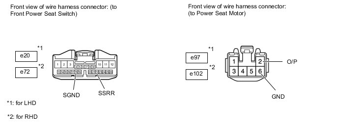
-
for LHD:
-
Disconnect the e20 switch connector.
-
Disconnect the e97 motor connector.
-
-
for RHD:
-
Disconnect the e72 switch connector.
-
Disconnect the e102 motor connector.
-
-
Measure the resistance according to the value(s) in the table below.
Standard resistance for LHD Tester Connection Condition Specified Condition e20-22 (SSRR) - e97-2 (O/P) Always Below 1 Ω e20-18 (SGND) - e97-6 (GND) Always Below 1 Ω e20-22 (SSRR) - e20-18 (SGND) Always 10 kΩ or higher e20-22 (SSRR) - Body ground Always 10 kΩ or higher e20-18 (SGND) - Body ground Always 10 kΩ or higher for RHD Tester Connection Condition Specified Condition e72-22 (SSRR) - e102-2 (O/P) Always Below 1 Ω e72-18 (SGND) - e102-6 (GND) Always Below 1 Ω e72-22 (SSRR) - e72-18 (SGND) Always 10 kΩ or higher e72-22 (SSRR) - Body ground Always 10 kΩ or higher e72-18 (SGND) - Body ground Always 10 kΩ or higher
NG
REPAIR OR REPLACE HARNESS OR CONNECTOR
OK
-
-
CHECK FRONT POWER SEAT SWITCH (POSITION CONTROL SENSOR)
-
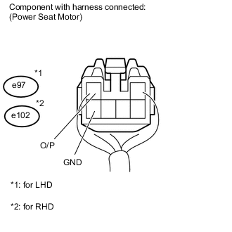
Measure the voltage according to the value(s) in the table below.
Standard voltage for LHD Tester Connection Switch Condition Specified Condition e97-2 (O/P) - e97-6 (GND) Reclining switch ON 0 to 8 V for RHD Tester Connection Switch Condition Specified Condition e102-2 (O/P) - e102-6 (GND) Reclining switch ON 0 to 8 V
NG
REPLACE FRONT SEAT POWER SWITCH Click here
OK
-
-
CHECK FRONT SEAT ADJUSTER ASSEMBLY
-
Temporarily replace the front seat adjuster assembly RH with a new or normally functioning one Click here.
-
Clear the DTC Click here.
-
Recheck the DTC Click here.
OK DTC B2658 is not output.
OK
END (FRONT SEAT ADJUSTER ASSEMBLY WAS DEFECTIVE)
NG
-
-
CHECK HARNESS AND CONNECTOR (FRONT POWER SEAT SWITCH - POWER SEAT MOTOR)
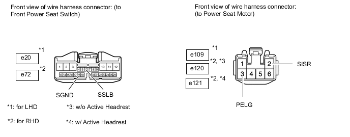
-
for LHD:
-
Disconnect the e20 switch connector.
-
Disconnect the e109 motor connector.
-
-
for RHD:
-
Disconnect the e72 switch connector.
-
Disconnect the e120*1 or e121*2 motor connector.
-
*1: w/ Active Headrest
-
*2: w/o Active Headrest
-
-
-
Measure the resistance according to the value(s) in the table below.
Standard resistance for LHD Tester Connection Condition Specified Condition e20-6 (SSLB) - e109-2 (SISR) Always Below 1 Ω e20-18 (SGND) - e109-3 (PELG) Always Below 1 Ω e20-6 (SSLB) - e20-18 (SGND) Always 10 kΩ or higher e20-6 (SSLB) - Body ground Always 10 kΩ or higher e20-18 (SGND) - Body ground Always 10 kΩ or higher for LHD Tester Connection Condition Specified Condition e72-6 (SSLB) - e120-2 (SISR)*1 Always Below 1 Ω e72-6 (SSLB) - e121-2 (SISR)*2 Always Below 1 Ω e72-18 (SGND) - e120-3 (PELG)*1 Always Below 1 Ω e72-18 (SGND) - e121-3 (PELG)*2 Always Below 1 Ω e72-6 (SSLB) - e72-18 (SGND) Always 10 kΩ or higher e72-6 (SSLB) - Body ground Always 10 kΩ or higher e72-18 (SGND) - Body ground Always 10 kΩ or higher
-
*1: w/ Active Headrest
-
*2: w/o Active Headrest
-
NG
REPAIR OR REPLACE HARNESS OR CONNECTOR
OK
-
-
CHECK FRONT POWER SEAT SWITCH (POSITION CONTROL SENSOR)
-
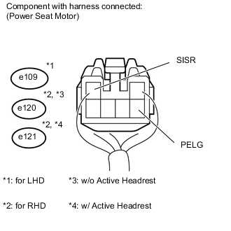
Measure the voltage according to the value(s) in the table below.
Standard voltage for LHD Tester Connection Switch Condition Specified Condition e109-2 (SISR) - e109-3 (PELG) Lumbar switch ON 0 to 8 V for RHD Tester Connection Switch Condition Specified Condition e120-2 (SISR) - e120-3 (PELG)*1 Lumbar switch ON 0 to 8 V e120-2 (SISR) - e120-3 (PELG)*2 Lumbar switch ON 0 to 8 V
-
*1: w/ Active Headrest
-
*2: w/o Active Headrest
-
NG
REPLACE FRONT SEAT POWER SWITCH Click here
OK
-
-
CHECK LUMBAR SUPPORT ADJUSTER ASSEMBLY
-
Temporarily replace the lumbar support adjuster assembly with a new or normally functioning one Click here.
-
Clear the DTC Click here.
-
Recheck the DTC Click here.
OK DTC B2658 is not output.
A
END (LUMBAR SUPPORT ADJUSTER ASSEMBLY WAS DEFECTIVE)
B
-
-
CHECK VEHICLE TYPE
-
Check the type of headrest.
Result Result Proceed to w/ Normal Headrest A w/ Folding Headrest B
B
CHECK HARNESS AND CONNECTOR (FRONT POWER SEAT SWITCH - POWER SEAT MOTOR) Click here
A
-
-
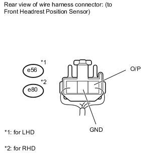
CHECK HARNESS AND CONNECTOR (FRONT POWER SEAT SWITCH RH - POWER SEAT MOTOR)
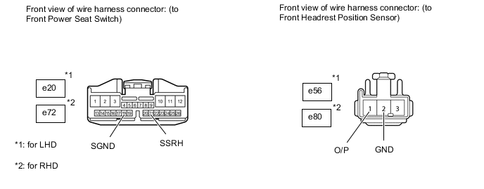
-
for LHD:
-
Disconnect the e20 switch connector.
-
Disconnect the e56 motor connector.
-
-
for RHD:
-
Disconnect the e72 switch connector.
-
Disconnect the e80 motor connector.
-
-
Measure the resistance according to the value(s) in the table below.
Standard resistance for LHD Tester Connection Condition Specified Condition e20-21 (SSRH) - e56-1 (O/P) Always Below 1 Ω e20-18 (SGND) - e56-2 (GND) Always Below 1 Ω e20-21 (SSRH) - e20-18 (SGND) Always 10 kΩ or higher e20-21 (SSRH) - Body ground Always 10 kΩ or higher e20-18 (SGND) - Body ground Always 10 kΩ or higher for RHD Tester Connection Condition Specified Condition e72-21 (SSRH) - e80-1 (O/P) Always Below 1 Ω e72-18 (SGND) - e80-2 (GND) Always Below 1 Ω e72-21 (SSRH) - e72-18 (SGND) Always 10 kΩ or higher e72-21 (SSRH) - Body ground Always 10 kΩ or higher e72-18 (SGND) - Body ground Always 10 kΩ or higher
NG
REPAIR OR REPLACE HARNESS OR CONNECTOR
OK
-
-
CHECK FRONT POWER SEAT SWITCH (POSITION CONTROL SENSOR)
-
Measure the voltage according to the value(s) in the table below.
Standard voltage for LHD Tester Connection Switch Condition Specified Condition e56-1 (O/P) - e56-2 (GND) Headrest switch ON 0 to 8 V for RHD Tester Connection Switch Condition Specified Condition e80-1 (O/P) - e80-2 (GND) Headrest switch ON 0 to 8 V
NG
REPLACE FRONT SEAT POWER SWITCH Click here
OK
-
-
CHECK FRONT SEAT HEADREST ADJUSTER SUB-ASSEMBLY
-
Temporarily replace the front seat headrest adjuster sub-assembly with a new or normally functioning one Click here.
-
Clear the DTC Click here.
-
Recheck the DTC Click here.
OK DTC B2658 is not output.
OK
END (FRONT SEAT ADJUSTER ASSEMBLY WAS DEFECTIVE)
NG
REPLACE FRONT SEAT POWER SWITCH Click here
-
-
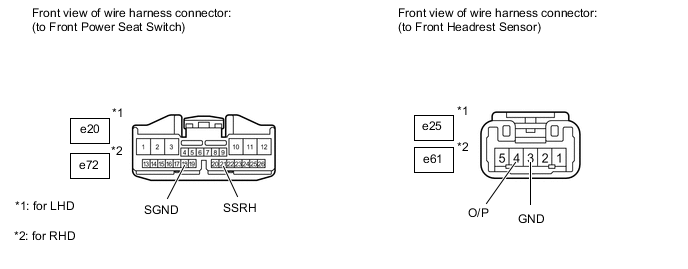
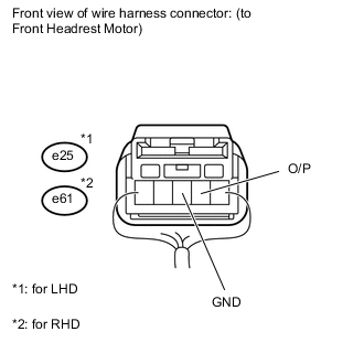
CHECK HARNESS AND CONNECTOR (FRONT POWER SEAT SWITCH - POWER SEAT MOTOR)
-
for LHD:
-
Disconnect the e20 switch connector.
-
Disconnect the e25 motor connector.
-
-
for RHD:
-
Disconnect the e72 switch connector.
-
Disconnect the e61 motor connector.
-
-
Measure the resistance according to the value(s) in the table below.
Standard resistance for LHD Tester Connection Condition Specified Condition e20-21 (SSRH) - e25-4 (O/P) Always Below 1 Ω e20-18 (SGND) - e25-3 (GND) Always Below 1 Ω e20-21 (SSRH) - e20-18 (SGND) Always 10 kΩ or higher e20-21 (SSRH) - Body ground Always 10 kΩ or higher e20-18 (SGND) - Body ground Always 10 kΩ or higher for RHD Tester Connection Condition Specified Condition e72-21 (SSRH) - e61-4 (O/P) Always Below 1 Ω e72-18 (SGND) - e61-3 (GND) Always Below 1 Ω e72-21 (SSRH) - e72-18 (SGND) Always 10 kΩ or higher e72-21 (SSRH) - Body ground Always 10 kΩ or higher e72-18 (SGND) - Body ground Always 10 kΩ or higher
NG
REPAIR OR REPLACE HARNESS OR CONNECTOR
OK
-
-
CHECK FRONT POWER SEAT SWITCH
-
Measure the voltage according to the value(s) in the table below.
Standard voltage for LHD Tester Connection Switch Condition Specified Condition e25-4 (O/P) - e25-3 (GND) Headrest switch ON 0 to 8 V for RHD Tester Connection Switch Condition Specified Condition e61-4 (O/P) - e61-3 (GND) Headrest switch ON 0 to 8 V
NG
REPLACE FRONT SEAT POWER SWITCH Click here
OK
-
-
REPLACE FRONT SEAT HEADREST ADJUSTER SUB-ASSEMBLY
-
Temporarily replace the front seat headrest adjuster sub-assembly with a new or normally functioning one Click here.
-
Clear the DTC Click here.
-
Recheck the DTC Click here.
OK DTC B2658 is not output.
OK
END (FRONT SEAT ADJUSTER ASSEMBLY WAS DEFECTIVE)
NG
REPLACE FRONT SEAT POWER SWITCH Click here
-