REAR POWER SEAT CONTROL SYSTEM TERMINALS OF ECU
-
CHECK POSITION CONTROL ECU LH

-
Disconnect the f24 and f41 ECU connectors.
-
Measure the voltage and resistance of the wire harness connectors.
Terminal No.
(Symbols)
Wiring Color Terminal Description Condition Specified Condition f24-1 (+B) - f24-6 (GND) L - W-B Battery Always 11 to 14 V f41-16 (SYSB) - f24-6 (GND) R - W-B Power source Always 11 to 14 V f24-6 (GND) - Body ground W-B - Body ground Ground Always Below 1 Ω f41-23 (SGND) - Body ground BR - Body ground Ground Always Below 1 Ω If the result is not as specified, there may be a malfunction on the wire harness side.
-
Reconnect the f24 and f41 ECU connectors.
-
Measure the voltage of the connectors.
Terminal No.
(Symbols)
Wiring Color Terminal Description Condition Specified Condition f24-3 (SLD+) - f24-6 (GND) B - W-B Sliding motor signal (forward) Seat moving forward using sliding switch 11 to 14 V Other Below 1 V f24-8 (SLD-) - f24-6 (GND) W - W-B Sliding motor signal (rearward) Seat moving rearward using sliding switch 11 to 14 V Other Below 1 V f24-5 (HUP) - f24-6 (GND) R - W-B Headrest motor signal (upward) Headrest moving upward using headrest switch 11 to 14 V Other Below 1 V f24-12 (HDWN) - f24-6 (GND) L - W-B Headrest motor signal (downward) Headrest moving downward using headrest switch 11 to 14 V Other Below 1 V f24-9 (MR+) - f24-6 (GND) Y - W-B Upper lumbar motor signal (forward) Seatback moving forward using upper lumbar switch 11 to 14 V Other Below 1 V f24-10 (MR-) - f24-6 (GND) R - W-B Upper lumbar motor signal (rearward) Seatback moving rearward using upper lumbar switch 11 to 14 V Other Below 1 V f24-2 (RCL+) - f24-6 (GND)* Y - W-B Reclining motor signal (forward) Seatback moving forward using reclining switch 11 to 14 V Other Below 1 V f24-7 (RCL-) - f24-6 (GND)* B - W-B Reclining motor signal (rearward) Seatback moving rearward using reclining switch 11 to 14 V Other Below 1 V f24-4 (OTO+) - f24-6 (GND)* L - W-B Ottoman motor signal (upward) Ottoman moving upward using ottoman switch 11 to 14 V Other Below 1 V f24-11 (OTO-) - f24-6 (GND)* G-B - W-B Ottoman motor signal (downward) Ottoman moving downward using ottoman switch 11 to 14 V f41-17 (PVCC) - f41-23 (SGND) Y - BR Position sensor power supply Power seat operation 7.2 to 8.8 V f41-5 (SSRS) - f41-23 (SGND) W - BR Slide direction position signal Slide operation 0 to 8 V f41-6 (SSRH) - f41-23 (SGND) R - BR Headrest position signal Headrest operation 0 to 8 V f41-7 (SSMR) - f41-23 (SGND) LG - BR Upper lumbar position signal Upper lumbar operation 0 to 8 V f41-8 (SSRR) - f41-23 (SGND)* G - BR Reclining position signal Reclining operation 0 to 8 V f41-9 (SSRO) - f41-23 (SGND)* G - BR Ottoman position signal Ottoman operation 0 to 8 V
-
*: w/ Ottoman (for RHD)
-
-
-
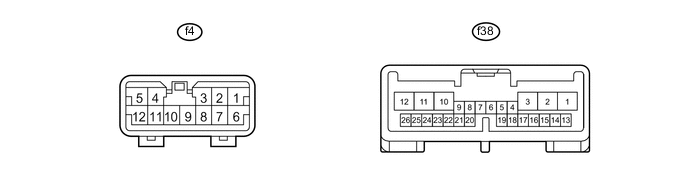
CHECK POSITION CONTROL ECU RH
-
Disconnect the f4 and f38 ECU connectors.
-
Measure the voltage and resistance of the wire harness connectors.
Terminal No.
(Symbols)
Wiring Color Terminal Description Condition Specified Condition f4-1 (+B) - f4-6 (GND) L - W-B Battery Always 11 to 14 V f38-16 (SYSB) - f4-6 (GND) R - W-B Power source Always 11 to 14 V f4-6 (GND) - Body ground W-B - Body ground Ground Always Below 1 Ω f38-23 (SGND) - Body ground BR - Body ground Ground Always Below 1 Ω f38-26 (SEL) - f38-25 (SEL2) B - B Right or left identification Always Below 1 Ω If the result is not as specified, there may be a malfunction on the wire harness side.
-
Reconnect the f4 and f38 ECU connectors.
-
Measure the voltage of the connectors.
Terminal No.
(Symbols)
Wiring Color Terminal Description Condition Specified Condition f4-3 (SLD+) - f4-6 (GND) R - W-B Sliding motor signal (forward) Seat moving forward using sliding switch 11 to 14 V Other Below 1 V f4-8 (SLD-) - f4-6 (GND) B - W-B Sliding motor signal (rearward) Seat moving rearward using sliding switch 11 to 14 V Other Below 1 V f4-5 (HUP) - f4-6 (GND) L - W-B Headrest motor signal (upward) Headrest moving upward using headrest switch 11 to 14 V Other Below 1 V f4-12 (HDWN) - f4-6 (GND) W - W-B Headrest motor signal (downward) Headrest moving downward using headrest switch 11 to 14 V Other Below 1 V f4-9 (MR+) - f4-6 (GND) P - W-B Upper lumbar motor signal (forward) Seatback moving forward using upper lumbar switch 11 to 14 V Other Below 1 V f4-10 (MR-) - f4-6 (GND) W - W-B Upper lumbar motor signal (rearward) Seatback moving rearward using upper lumbar switch 11 to 14 V Other Below 1 V f4-2 (RCL+) - f4-6 (GND)* Y - W-B Reclining motor signal (forward) Seatback moving forward using reclining switch 11 to 14 V Other Below 1 V f4-7 (RCL-) - f4-6 (GND)* B - W-B Reclining motor signal (rearward) Seatback moving rearward using reclining switch 11 to 14 V Other Below 1 V f4-4 (OTO+) - f4-6 (GND)* L - W-B Ottoman motor signal (upward) Ottoman moving upward using ottoman switch 11 to 14 V Other Below 1 V f4-11 (OTO-) - f4-6 (GND)* G-B - W-B Ottoman motor signal (downward) Ottoman moving downward using ottoman switch 11 to 14 V Other Below 1 V f38-17 (PVCC) - f38-23 (SGND) Y - BR Position sensor power supply Power seat operation 7.2 to 8.8 V f38-5 (SSRS) - f38-23 (SGND) W - BR Slide direction position signal Slide operation 0 to 8 V f38-6 (SSRH) - f38-23 (SGND) BE - BR Headrest position signal Headrest operation 0 to 8 V f38-7 (SSMR) - f38-23 (SGND) BE - BR Upper lumbar position signal Upper lumbar operation 0 to 8 V f38-8 (SSRR) - f38-23 (SGND)* Y - BR Reclining position signal Reclining operation 0 to 8 V f38-9 (SSRO) - f38-23 (SGND)* G - BR Ottoman position signal Ottoman operation 0 to 8 V
-
*: w/ Ottoman (for LHD)
-
-
-
CHECK REAR DOOR ECU LH

-
Disconnect the O14 ECU connector.
-
Measure the voltage and resistance of the wire harness connector.
Terminal No.
(Symbols)
Wiring Color Terminal Description Condition Specified Condition O14-11 (CPUB) - O14-1 (GND) R - W-B Battery (ECU power source) Always 11 to 14 V O14-6 (BDR) - O14-1 (GND) L - W-B Battery (ECU power source) Always 11 to 14 V O14-3 (SIG) - O14-1 (GND) Y - W-B Ignition power supply Engine switch off Below 1 V Engine switch on (IG) 11 to 14 V O14-1 (GND) - Body ground W-B - Body ground Ground Always Below 1 Ω If the result is not as specified, there may be a malfunction on the wire harness side.
-
Reconnect the O14 ECU connector.
-
Measure the voltage of the connector.
Terminal No.
(Symbols)
Wiring Color Terminal Description Condition Specified Condition O15-19 (M) - O15-29 (MSWE) B - P Memory M switch signal Memory M switch OFF Pulse generation Memory M switch ON Below 1 V O15-18 (CAN) - O15-29 (MSWE) BE - P Memory C switch signal Memory C switch OFF Pulse generation Memory C switch ON Below 1 V O15-22 (SET) - O15-29 (MSWE) W - P Memory SET switch signal Memory SET switch OFF Pulse generation Memory SET switch ON Below 1 V If the result is not as specified, the ECU may have a malfunction.
-
-
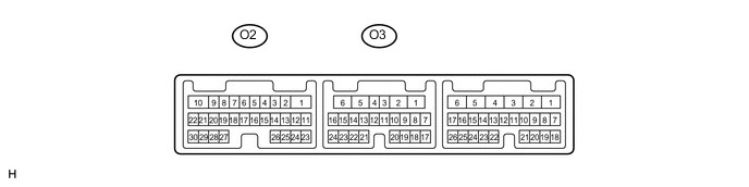
CHECK REAR DOOR ECU RH
-
Disconnect the O3 ECU connector.
-
Measure the voltage and resistance of the wire harness connector.
Terminal No.
(Symbols)
Wiring Color Terminal Description Condition Specified Condition O3-11 (CPUB) - O3-1 (GND) R - W-B Battery (ECU power source) Always 11 to 14 V O3-6 (BDR) - O3-1 (GND) L - W-B Battery (ECU power source) Always 11 to 14 V O3-3 (SIG) - O3-1 (GND) GR - W-B Ignition power supply Engine switch off Below 1 V Engine switch on (IG) 11 to 14 V O3-1 (GND) - Body ground W-B - Body ground Ground Always Below 1 Ω If the result is not as specified, there may be a malfunction on the wire harness side.
-
Reconnect the O3 ECU connector.
-
Measure the voltage of the connector.
Terminal No.
(Symbols)
Wiring Color Terminal Description Condition Specified Condition O2-19 (M) - O2-29 (MSWE) B - P Memory M switch signal Memory M switch OFF Pulse generation Memory M switch ON Below 1 V O2-18 (CAN) - O2-29 (MSWE) BE - P Memory C switch signal Memory C switch OFF Pulse generation Memory C switch ON Below 1 V O2-22 (SET) - O2-29 (MSWE) W - P Memory SET switch signal Memory SET switch OFF Pulse generation Memory SET switch ON Below 1 V If the result is not as specified, the ECU may have a malfunction.
-