POWER WINDOW CONTROL SYSTEM Front Passenger Side Power Window Auto Up / Down Function does not Operate with Front Passenger Side Power Window Switch
DESCRIPTION
-
If the AUTO UP/DOWN function does not operate, the cause may be one or more of the following:
-
ECU in the power window regulator motor determines that the power window regulator motor has not been initialized.
-
The power window regulator switch has a malfunction.
-
The Hall-IC in the power window regulator motor have a malfunction.
-
The wiring between the power window regulator switch and the power window regulator motor is open or short.
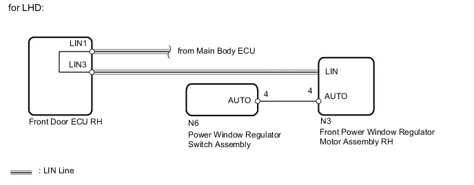
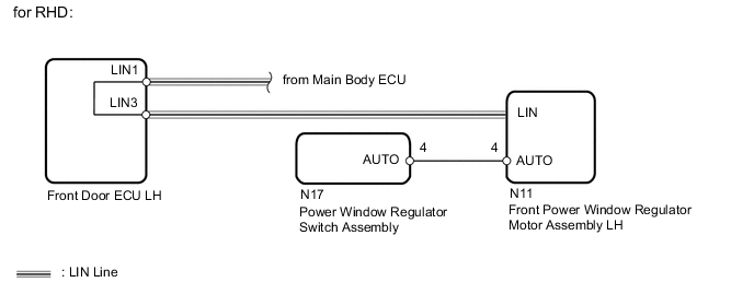
WIRING DIAGRAM
CAUTION / NOTICE / HINT
Note
-
The power window control system uses the LIN communication system. Inspect the communication function by following How to Proceed with Troubleshooting. Troubleshoot the power window control system after confirming that the communication system is functioning properly Click here.
-
If the front power window regulator motor assembly RH*1, LH*2 has been replaced with a new one, initialize the power window control system Click here.
-
Check that the "P Window Auto Up" and "P Window Auto Down" power window control system customize settings are "ON" before proceeding with work Click here.
-
After the catch protection function operates, the auto operation is not performed the first time auto up is performed. All auto up operations performed after the first operate normally
Tech Tips
If the pulse sensor built into the front power window regulator motor assembly RH*1, LH*2 is malfunctioning, the power window control system enters fail-safe mode. The remote up and down and auto up and down functions cannot be operated during fail-safe mode. However, the power window can be closed by holding the power window regulator switch assembly at the auto up position, and opened manually by pushing down the power window regulator switch assembly Click here.
-
*1: for LHD
-
*2: for RHD
PROCEDURE
-
CHECK FOR DTC
-
Check for DTCs.
Result: Result Proceed to B2311 is output A B2312 is output B B2313 is output C LIN communication system DTC is output D DTC is not output E
A 
GO TO DTC B2311 Click here
B
GO TO DTC B2312 Click here
C
GO TO DTC B2313 Click here
D
GO TO LIN COMMUNICATION SYSTEM Click here
E 
-
-
CHECK MANUAL UP / DOWN FUNCTION (FRONT PASSENGER SIDE SWITCH)
-
Check that the manual UP/DOWN function using the power window regulator switch can operate the driver door power window.
OK Manual UP/DOWN function operates normally.
NG
OTHER PROBLEM Click here
OK
-
-
READ VALUE USING INTELLIGENT TESTER (FRONT PASSENGER SIDE MOTOR)
-
Connect the intelligent tester to the DLC3.
-
Turn the engine switch on (IG).
-
Turn ON the intelligent tester.
-
Enter the following menus.
-
Select: Body / P-Door Motor / Data List /
-
-
According to the display on tester, read the "Data List".
P-Door Motor: Tester Display Measurement Item/Range Normal Condition Diagnostic Note P Door P/W Auto SW Front passenger side power window remote auto UP/DOWN switch signal / ON or OFF ON: Front passenger side power window remote auto UP/DOWN switch on master switch operated
OFF: Front passenger side power window switch on master switch not operated
- OK Tester display changes normally when front passenger side power window switch is operated. Result: Result Proceed to NG A OK (for LHD) B OK (for RHD) C
B
REPLACE FRONT POWER WINDOW REGULATOR MOTOR ASSEMBLY RH Click here
C
REPLACE FRONT POWER WINDOW REGULATOR MOTOR ASSEMBLY LH Click here
A
-
-
CHECK HARNESS AND CONNECTOR (FRONT PASSENGER SIDE SWITCH - FRONT PASSENGER SIDE MOTOR)
-
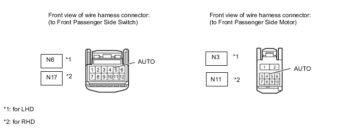
Disconnect the N6*1 or N17*2 switch connector.
-
Disconnect the N3*1 or N11*2 motor connector.
-
Measure the resistance according to the value(s) in the table below.
Standard resistance for LHD: Tester Connection Condition Specified Condition N6-4 (AUTO) - N3-4 (AUTO) Always Below 1 Ω N6-4 (AUTO) or N3-4 (AUTO) - Body ground Always 10 kΩ or higher for RHD: Tester Connection Condition Specified Condition N17-4 (AUTO) - N11-4 (AUTO) Always Below 1 Ω N17-4 (AUTO) or N11-4 (AUTO) - Body ground Always 10 kΩ or higher
NG
REPAIR OR REPLACE HARNESS OR CONNECTOR
OK
-
-
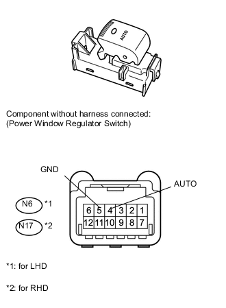
INSPECT POWER WINDOW REGULATOR SWITCH ASSEMBLY (for Front Passenger Side)
-
Remove the switch.
-
Measure the resistance of the switch when the switch is operated.
Standard resistance for LHD: Tester Connection Switch Condition Specified Condition N6-4 (AUTO) - N6-5 (GND) AUTO UP/DOWN operation Below 1 Ω for RHD: Tester Connection Switch Condition Specified Condition N17-4 (AUTO) - N17-5 (GND) AUTO UP/DOWN operation Below 1 Ω Result: Result Proceed to NG A OK (for LHD) B OK (for RHD) C
A
REPLACE FRONT POWER WINDOW REGULATOR SWITCH ASSEMBLY (for Front Passenger Side) Click here
B
REPLACE FRONT POWER WINDOW REGULATOR MOTOR ASSEMBLY RH Click here
C
REPLACE FRONT POWER WINDOW REGULATOR MOTOR ASSEMBLY LH Click here
-