POWER WINDOW CONTROL SYSTEM Front Passenger Side Power Window does not Operate with Front Passenger Side Power Window Switch
DESCRIPTION
-
If the manual UP/DOWN function does not operate, there may be a malfunction in the power window regulator switch assembly, front power window regulator motor assembly RH or wire harness.
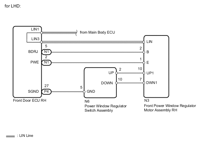
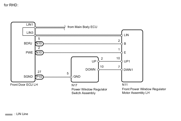
WIRING DIAGRAM
PROCEDURE
-
CHECK LIN COMMUNICATION SYSTEM
-
Check for LIN communication system DTCs related to the power window control system.
Result: Result Proceed to DTC is output A DTC is not output B
A 
GO TO LIN COMMUNICATION SYSTEM Click here
B 
-
-
CHECK FOR DTC (B2312)
-
Check if DTC B2312 is output.
Result: Result Proceed to DTC is output A DTC is not output B
A
GO TO DTC B2312 Click here
B
-
-
READ VALUE USING INTELLIGENT TESTER (FRONT PASSENGER SIDE MOTOR)
-
Connect the intelligent tester to the DLC3.
-
Turn the engine switch on (IG).
-
Turn ON the intelligent tester.
-
Enter the following menus.
-
Select: Body / P-Door Motor / Data List /
-
-
According to the display on tester, read the "Data List".
P-Door Motor: Tester Display Measurement Item/Range Normal Condition Diagnostic Note P Door P/W Up SW Front passenger side power window remote manual UP switch signal / ON or OFF ON: Front passenger side power window remote manual UP switch on master switch operated
OFF: Front passenger side power window switch on master switch not operated
- P Door P/W Down SW Front passenger side power window remote manual DOWN switch signal / ON or OFF ON: Front passenger side power window remote manual DOWN switch on master switch operated
OFF: Front passenger side power window switch on master switch not operated
- OK Tester display changes normally when front passenger side power window switch is operated. Result: Result Proceed to NG A OK (for LHD) B OK (for RHD) C
B
REPLACE FRONT POWER WINDOW REGULATOR MOTOR ASSEMBLY RH Click here
C
REPLACE FRONT POWER WINDOW REGULATOR MOTOR ASSEMBLY LH Click here
A
-
-
CHECK HARNESS AND CONNECTOR (FRONT PASSENGER SIDE DOOR ECU - FRONT PASSENGER SIDE SWITCH)
-
Disconnect the P4*1 or P10*2 ECU connector.
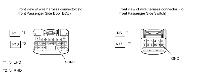
-
Disconnect the N6*1 or N17*2 switch connector.
-
Measure the resistance according to the value(s) in the table below.
Standard resistance for LHD: Tester Connection Condition Specified Condition P4-27 (SGND) - N6-5 (GND) Always Below 1 Ω P4-27 (SGND) or N6-5 (GND) - Body ground Always 10 kΩ or higher for RHD: Tester Connection Condition Specified Condition P10-27 (SGND) - N17-5 (GND) Always Below 1 Ω P10-27 (SGND) or N17-5 (GND) - Body ground Always 10 kΩ or higher
NG
REPAIR OR REPLACE HARNESS OR CONNECTOR
OK
-
-
CHECK HARNESS AND CONNECTOR (FRONT PASSENGER SIDE DOOR ECU - FRONT PASSENGER SIDE MOTOR)
-
Disconnect the N1*1 or N10*2 ECU connector.
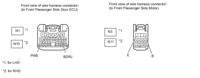
-
Disconnect the N3*1 or N11*2 motor connector.
-
Measure the resistance according to the value(s) in the table below.
Standard resistance for LHD: Tester Connection Condition Specified Condition N1-5 (BDRJ) - N3-2 (B) Always Below 1 Ω N1-2 (PWE) - N3-1 (E) Always Below 1 Ω N1-5 (BDRJ) or N3-2 (B) - Body ground Always 10 kΩ or higher N1-2 (PWE) or N3-1 (E) - Body ground Always 10 kΩ or higher for RHD: Tester Connection Condition Specified Condition N10-5 (BDRJ) - N11-2 (B) Always Below 1 Ω N10-2 (PWE) - N11-1 (E) Always Below 1 Ω N10-5 (BDRJ) or N11-2 (B) - Body ground Always 10 kΩ or higher N10-2 (PWE) or N11-1 (E) - Body ground Always 10 kΩ or higher
NG
REPAIR OR REPLACE HARNESS OR CONNECTOR
OK
-
-
CHECK HARNESS AND CONNECTOR (FRONT PASSENGER SIDE SWITCH - FRONT PASSENGER SIDE MOTOR)
-
Disconnect the N6*1 or N17*2 switch connector.
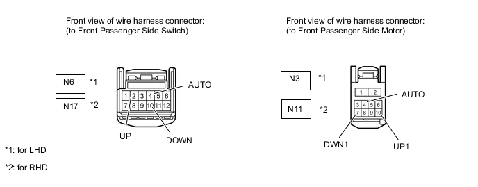
-
Disconnect the N3*1 or N11*2 motor connector.
-
Measure the resistance according to the value(s) in the table below.
Standard resistance for LHD: Tester Connection Condition Specified Condition N6-2 (UP) - N3-10 (UP1) Always Below 1 Ω N6-10 (DOWN) - N3-7 (DWN1) Always Below 1 Ω N6-2 (UP) or N3-10 (UP1) - Body ground Always 10 kΩ or higher N6-10 (DOWN) or N3-7 (DWN1) - Body ground Always 10 kΩ or higher for RHD: Tester Connection Condition Specified Condition N17-2 (UP) - N11-10 (UP1) Always Below 1 Ω N17-10 (DOWN) - N11-7 (DWN1) Always Below 1 Ω N17-2 (UP) or N11-10 (UP1) - Body ground Always 10 kΩ or higher N17-10 (DOWN) or N11-7 (DWN1) - Body ground Always 10 kΩ or higher
NG
REPAIR OR REPLACE HARNESS OR CONNECTOR
OK
-
-
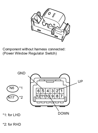
INSPECT POWER WINDOW REGULATOR SWITCH ASSEMBLY (for Front Passenger Side)
-
Remove the switch.
-
Measure the resistance of the switch when the switch is operated.
Standard resistance for LHD: Tester Connection Switch Condition Specified Condition N6-2 (UP) - N6-5 (GND) Manual UP operation Below 1 Ω N6-10 (DOWN) - N6-5 (GND) Manual DOWN operation Below 1 Ω for RHD: Tester Connection Switch Condition Specified Condition N17-2 (UP) - N17-5 (GND) Manual UP operation Below 1 Ω N17-10 (DOWN) - N17-5 (GND) Manual DOWN operation Below 1 Ω Result: Result Proceed to NG A OK (for LHD) B OK (for RHD) C
A
REPLACE FRONT POWER WINDOW REGULATOR SWITCH ASSEMBLY (for Front Passenger Side) Click here
B
REPLACE FRONT POWER WINDOW REGULATOR MOTOR ASSEMBLY RH Click here
C
REPLACE FRONT POWER WINDOW REGULATOR MOTOR ASSEMBLY LH Click here
-