COMBINATION METER DISASSEMBLY
PROCEDURE
-
REMOVE NO. 1 COMBINATION METER BRACKET
-
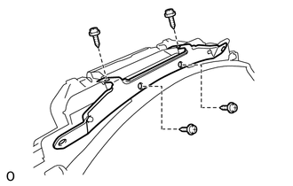
Remove the 4 screws and No. 1 combination meter bracket.
-
-
REMOVE COMBINATION METER GLASS
-
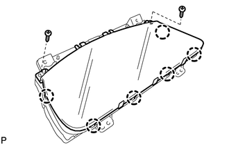
Remove the 2 screws.
-
Detach the 6 claws and remove the combination meter glass.
-
-
REMOVE COMBINATION METER COVER
-
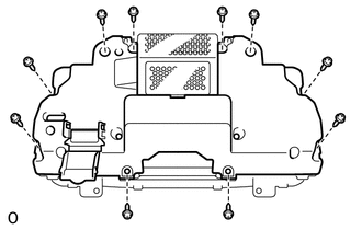
Remove the 10 screws and combination meter cover.
-
-
REMOVE METER DISPLAY PANEL
-
Lift the 3 connector locks upward to release the locks and disconnect the 2 wire harnesses from the 3 connectors.
Note
-
Do not remove the connector lock from the meter ECU.
-
Do not forcibly pull the wire harness from the connector.
-
Disconnect the wire harness from the connector by holding both ends and pulling straight up.
-
Do not scratch or dirty the contacts of the wire harness.
-
-
Remove the meter display panel from the meter ECU.
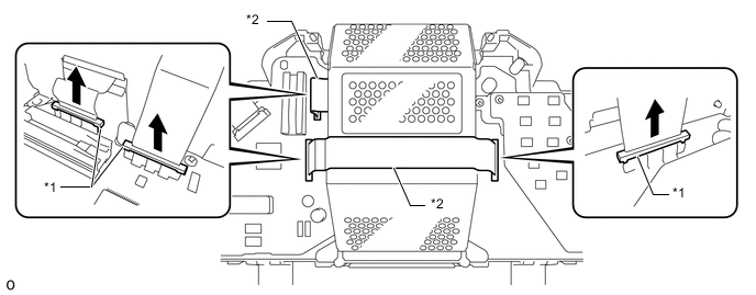
Text in Illustration *1 Connector Lock *2 Wire Harness 
Upward - -
-