DOOR CONTROL SWITCH INSPECTION
PROCEDURE
-
INSPECT DOOR CONTROL SWITCH ASSEMBLY
-
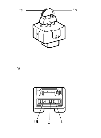
Text in Illustration *a Component without harness connected
(Door Control Switch Assembly)
*b Lock *c Unlock Measure the resistance according to the value(s) in the table below.
Standard resistance Tester Connection Switch Condition Specified Condition 2 (L) - 3 (E) Lock Below 1 Ω 2 (L) - 3 (E)
4 (UL) - 3 (E)
OFF 10 kΩ or higher 4 (UL) - 3 (E) Unlock Below 1 Ω
-
If the result is not as specified, replace the door control switch assembly.
-
-
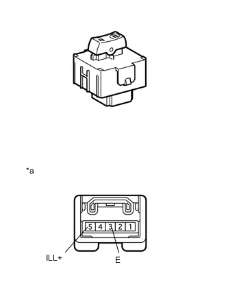
Text in Illustration *a Component without harness connected
(Door Control Switch Assembly)
When terminal 5 (ILL+) of the connector is connected to the positive (+) battery terminal and terminal 3 (E) is connected to the negative (-) battery terminal, check that the indicator (LED) illuminates.
Tech Tips
If result is not as specified, replace the door control switch assembly.
-