METER / GAUGE SYSTEM, Diagnostic DTC:B1500
| DTC Code | DTC Name |
|---|---|
| B1500 | Fuel Sender Open Detected |
DESCRIPTION
This DTC is output when the No. 1 meter ECU detects the fuel sender gauge malfunction via the CAN.
| DTC Code | DTC Detection Condition | Trouble Area |
|---|---|---|
| B1500 | When No. 1 meter ECU detects fuel sender gauge malfunction |
|
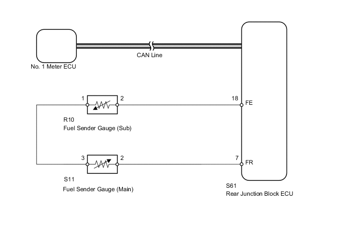
WIRING DIAGRAM
PROCEDURE
-
CHECK CAN COMMUNICATION SYSTEM
-
Check for the DTC Click here.
Result: Result Proceed to CAN communication system DTC is not output A CAN communication system (for LHD) DTC is output B CAN communication system (for RHD) DTC is output C
B 
Go to CAN COMMUNICATION SYSTEM Click here
C
Go to CAN COMMUNICATION SYSTEM Click here
A 
-
-
PERFORM ACTIVE TEST USING INTELLIGENT TESTER (FUEL RECEIVER GAUGE)
-
Operate the intelligent tester according to the steps on the display and select "Active Test".
Combination Meter: Tester Display Test Part Control Range Fuel Meter Operation Fuel receiver gauge EMPTY, 1/2 or FULL OK Needle indication is normal.
NG
REPLACE NO. 1 METER ECU
OK
-
-
READ VALUE USING INTELLIGENT TESTER (FUEL SENDER GAUGE)
-
Operate the intelligent tester according to the display and select "Data List".
Combination Meter: Tester Display Measurement Item/Range Normal Condition Diagnostic Note Fuel Input Fuel sender gauge (main) input signal/Min.: 0, Max.: 127.5 Fuel sender input value Unit: L OK Fuel value displayed on tester is almost the same as needle indication.
OK
REPLACE NO. 1 METER ECU
NG
-
-
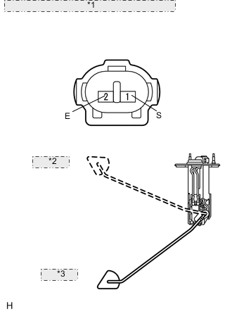
INSPECT FUEL SENDER GAUGE ASSEMBLY (MAIN)
*1 Component without harness connected: (Fuel Sender Gauge (Main)) *2 F (Upper) *3 E (Lower)
-
Remove the fuel sender gauge (main).
-
Measure the resistance according to the value(s) in the table below.
Standard resistance Tester Connection Condition Specified Condition 1 (FE) - 2 (S) Float level is F (upper) 6.5 to 8.5 Ω Between float level is F (upper) and E (lower) 91.0 to 102.2 Ω Float level is E (lower) 184.8 to 188.8 Ω
NG
REPLACE FUEL SENDER GAUGE ASSEMBLY (MAIN) Click here
OK
-
-
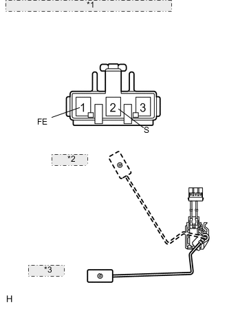
INSPECT FUEL SENDER GAUGE ASSEMBLY (SUB)
*1 Component without harness connected: (Fuel Sender Gauge (Sub)) *2 F (Upper) *3 E (Lower)
-
Remove the fuel sender gauge (sub).
-
Measure the resistance according to the value(s) in the table below.
Standard resistance Tester Connection Condition Specified Condition 1 (S) - 2 (E) Float level is F (upper) 6.5 to 8.5 Ω Between float level is F (upper) and E (lower) 112.7 to 125.7 Ω Float level is E (lower) 220.7 to 225.7 Ω
NG
REPLACE FUEL SENDER GAUGE ASSEMBLY (SUB) Click here
OK
-
-
CHECK HARNESS AND CONNECTOR (REAR JUNCTION BLOCK - FUEL SENDER GAUGE)
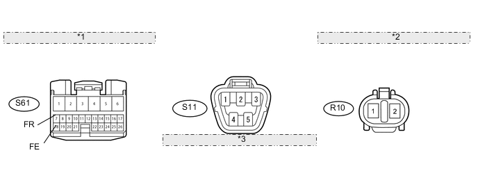
*1 Front view of wire harness connector: (to Rear Junction Block ECU) *2 Front view of wire harness connector: (to Fuel Sender Gauge (Sub)) *3 Front view of wire harness connector: (to Fuel Sender Gauge (Main))
-
Disconnect the S61 junction block connector.
-
Disconnect the S11 and R10 gauge connectors.
-
Measure the resistance according to the value(s) in the table below.
Standard resistance Tester Connector Condition Specified Condition S61-7 (FR) - S11-2 Always Below 1 Ω S61-18 (FE) - R10-2 S61-7 (FR) or S11-2 - Body ground Always 10 kΩ or higher S61-18 (FE) or R10-2 - Body ground
NG
REPAIR OR REPLACE HARNESS OR CONNECTOR
OK
-
-
CHECK HARNESS AND CONNECTOR (FUEL SENDER GAUGE (MAIN) - FUEL SENDER GAUGE (SUB))
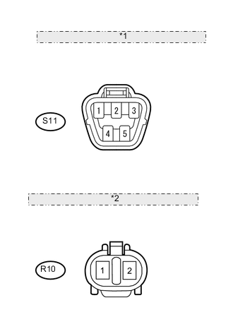
*1 Front view of wire harness connector: (to Fuel Sender Gauge (Main)) *2 Front view of wire harness connector: (to Fuel Sender Gauge (Sub))
-
Disconnect the S11 and R10 gauge connectors.
-
Measure the resistance according to the value(s) in the table below.
Standard resistance Tester Connection Condition Specified Condition S11-3 - R10-1 Always Below 1 Ω S11-3 or R10-1 - Body ground Always 10 kΩ or higher
NG
REPAIR OR REPLACE HARNESS OR CONNECTOR
OK
-
-
REPLACE NO. 1 METER ECU
-
Temporarily replace the No. 1 meter ECU with a new one.
NEXT
-
-
CHECK NO. 1 METER ECU (FUEL RECEIVER GAUGE)
-
Check that the operation of the fuel sender gauge in the meter returns to normal Click here.
OK Operation of the fuel sender gauge returns to normal.
OK
END (NO. 1 METER ECU IS DEFECTIVE)
NG
REPLACE LUGGAGE ROOM JUNCTION BLOCK ASSEMBLY (REAR JUNCTION BLOCK ECU)
-