POWER DOOR LOCK CONTROL SYSTEM Double Lock Function does not Operate Properly
DESCRIPTION
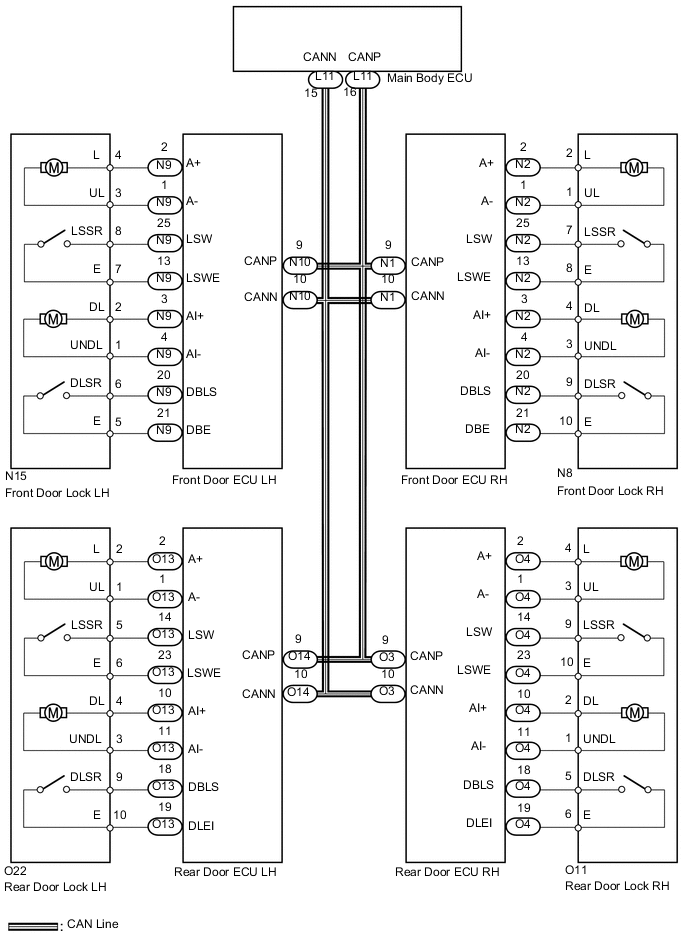
All the doors except the luggage compartment door have the double lock function. This system is set and unset by the main body ECU. When the main body ECU sends a request signal to each door ECU to set or unset the double lock function, the double lock motor built into each door lock operates.
WIRING DIAGRAM
PROCEDURE
-
CHECK WIRELESS DOOR LOCK CONTROL SYSTEM
-
Check that the doors can be locked and unlocked normally using the wireless operation.
OK Doors can be locked and unlocked normally using wireless operation.
NG 
GO TO WIRELESS DOOR LOCK CONTROL SYSTEM Click here
OK 
-
-
PERFORM ACTIVE TEST USING INTELLIGENT TESTER (DOUBLE DOOR LOCK MOTOR)
-
Select the Active Test, use the intelligent tester to generate a control command, and then check that the double door lock motor operates normally.
Driver Door (Front door ECU LH*1) (Front door ECU RH*2) Tester Display Test Part Control Range Diagnostic Note Double Lock Unset Operate double lock motor UNSET or SET - Tech Tips
*1: for LHD
*2: for RHD
OK Double door lock motor operates normally.
NG 
INSPECT FRONT DOOR LOCK ASSEMBLY (DRIVER SIDE DOUBLE DOOR LOCK MOTOR) Click here
OK
-
-
PERFORM ACTIVE TEST USING INTELLIGENT TESTER (DOUBLE DOOR LOCK MOTOR)
-
Select the Active Test, use the intelligent tester to generate a control command, and then check that the double door lock motor operates normally.
Passenger Door (Front door ECU RH*1) (Front door ECU LH*2) Tester Display Test Part Control Range Diagnostic Note Double Lock Unset Operate double lock motor UNSET or SET - Tech Tips
*1: for LHD
*2: for RHD
OK Double door lock motor operates normally.
NG
INSPECT FRONT DOOR LOCK ASSEMBLY (FRONT PASSENGER SIDE DOUBLE DOOR LOCK MOTOR) Click here
OK
-
-
PERFORM ACTIVE TEST USING INTELLIGENT TESTER (DOUBLE DOOR LOCK MOTOR)
-
Select the Active Test, use the intelligent tester to generate a control command, and then check that the double door lock motor operates normally.
Rear Left Door (Rear door ECU LH) Tester Display Test Part Control Range Diagnostic Note Double Lock Unset Operate double lock motor UNSET or SET - OK Double door lock motor operates normally.
NG
INSPECT REAR DOOR LOCK ASSEMBLY LH (DOUBLE DOOR LOCK MOTOR) Click here
OK
-
-
PERFORM ACTIVE TEST USING INTELLIGENT TESTER (DOUBLE DOOR LOCK MOTOR)
-
Select the Active Test, use the intelligent tester to generate a control command, and then check that the double door lock motor operates normally.
Rear Right Door (Rear door ECU RH) Tester Display Test Part Control Range Diagnostic Note Double Lock Unset Operate double lock motor UNSET or SET - OK Double door lock motor operates normally.
OK
REPLACE MAIN BODY ECU
NG
INSPECT REAR DOOR LOCK ASSEMBLY RH (DOUBLE DOOR LOCK MOTOR) Click here
-
-
INSPECT FRONT DOOR LOCK ASSEMBLY (DRIVER SIDE DOUBLE DOOR LOCK MOTOR)
-
for LHD:

for LHD *1 Component without harness connected: (Front Door Lock LH) *2 Unlock *3 Lock
-
Apply battery voltage to the door lock and check operation of the door lock motor.
OK Measurement Condition Specified Condition Battery positive (+) → Terminal N15-4 (L)
Battery negative (-) → Terminal N15-3 (UL)
Lock -
Apply battery voltage to the door lock motor and check the operation of the double door lock motor.
OK Measurement Condition Specified Condition Battery positive (+) → Terminal N15-2 (DL)
Battery negative (-) → Terminal N15-1 (UNDL)
Set Battery positive (+) → Terminal N15-1 (UNDL)
Battery negative (-) → Terminal N15-2 (DL)
Unset -
While the double locking system is set, check that the doors cannot be unlocked by operating the control cable.
-
-
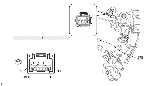
for RHD:

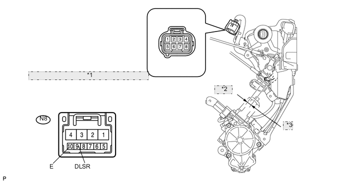
for RHD *1 Component without harness connected: (Front Door Lock RH) *2 Unlock *3 Lock
-
Apply battery voltage to the door lock and check operation of the door lock motor.
OK Measurement Condition Specified Condition Battery positive (+) → Terminal N8-2 (L)
Battery negative (-) → Terminal N8-1 (UL)
Lock -
Apply battery voltage to the door lock motor and check the operation of the double door lock motor.
OK Measurement Condition Specified Condition Battery positive (+) → Terminal N8-4 (DL)
Battery negative (-) → Terminal N8-3 (UNDL)
Set Battery positive (+) → Terminal N8-3 (UNDL)
Battery negative (-) → Terminal N8-4 (DL)
Unset -
While the double locking system is set, check that the doors cannot be unlocked by operating the control cable.
-
NG
REPLACE FRONT DOOR LOCK ASSEMBLY (for Driver Side) Click here
OK
-
-
READ VALUE USING INTELLIGENT TESTER (DOUBLE DOOR LOCK POSITION SWITCH)
-
Use the Data List to check if the double door lock position switch is functioning properly.
Driver Door (Front door ECU LH*1) (Front door ECU RH*2) Tester Display Measurement Item/Display Normal Condition Diagnostic Note Double Lock Position SW Driver side double door lock position switch signal / ON or OFF ON: Driver side double door lock is unset
OFF: Driver side double door lock is set
- Tech Tips
*1: for LHD
*2: for RHD
OK ON (driver side double door lock is unset) appears on screen.
OK
REPLACE FRONT DOOR ECU (for Driver Side) Click here
NG
-
-
INSPECT FRONT DOOR LOCK ASSEMBLY (DRIVER SIDE DOUBLE DOOR LOCK POSITION SWITCH)
-
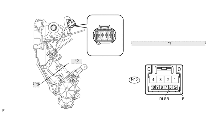
for LHD:
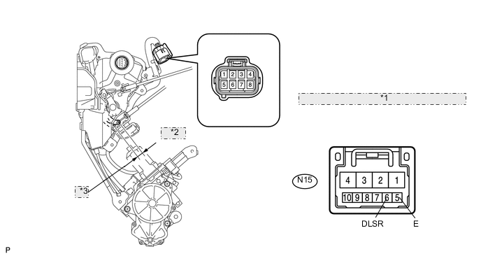
for LHD *1 Component without harness connected: (Front Door Lock LH) *2 Unlock *3 Lock
-
Measure the resistance according to the value(s) in the table below.
Standard resistance Tester Connection Switch Condition Specified Condition N15-6 (DLSR) - N15-5 (E) Set Below 1 Ω N15-6 (DLSR) - N15-5 (E) Unset 10 kΩ or higher
-
-
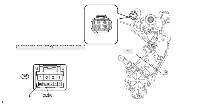
for RHD:
for RHD *1 Component without harness connected: (Front Door Lock RH) *2 Unlock *3 Lock
-
Measure the resistance according to the value(s) in the table below.
Standard resistance Tester Connection Switch Condition Specified Condition N8-9 (DLSR) - N8-10 (E) Set Below 1 Ω N8-9 (DLSR) - N8-10 (E) Unset 10 kΩ or higher
-
NG
REPLACE FRONT DOOR LOCK ASSEMBLY (for Driver Side) Click here
OK
-
-
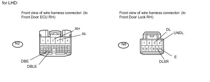
CHECK HARNESS AND CONNECTOR (FRONT DOOR LOCK - FRONT DOOR ECU)
-
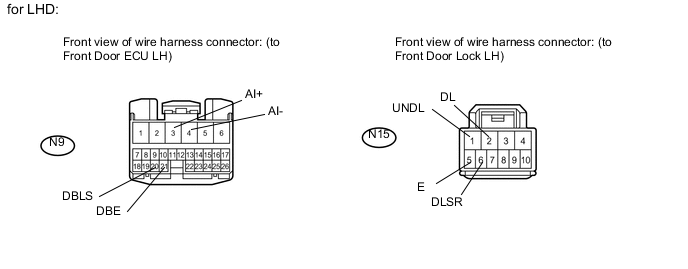
for LHD:
-
Disconnect the N9 ECU connector.
-
Disconnect the N15 door lock connector.
-
Measure the resistance according to the value(s) in the table below.
Standard resistance Tester Connection Condition Specified Condition N9-3 (AI+) - N15-2 (DL) Always Below 1 Ω N9-4 (AI-) - N15-1 (UNDL) Always Below 1 Ω N9-20 (DBSL) - N15-6 (DLSR) Always Below 1 Ω N9-21 (DBE) - N15-5 (E) Always Below 1 Ω N9-3 (AI+) - Body ground Always 10 kΩ or higher N9-4 (AI-) - Body ground Always 10 kΩ or higher N9-20 (DBSL) - Body ground Always 10 kΩ or higher N9-21 (DBE) - Body ground Always 10 kΩ or higher
-
-
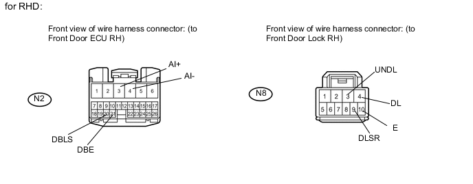
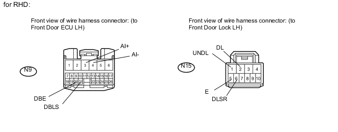
for RHD:
-
Disconnect the N2 ECU connector.
-
Disconnect the N8 door lock connector.
-
Measure the resistance according to the value(s) in the table below.
Standard resistance Tester Connection Condition Specified Condition N2-3 (AI+) - N8-4 (DL) Always Below 1 Ω N2-4 (AI-) - N8-3 (UNDL) Always Below 1 Ω N2-20 (DBSL) - N8-9 (DLSR) Always Below 1 Ω N2-21 (DBE) - N8-10 (E) Always Below 1 Ω N2-5 (AI+) - Body ground Always 10 kΩ or higher N2-6 (AI-) - Body ground Always 10 kΩ or higher N2-3 (DBSL) - Body ground Always 10 kΩ or higher N2-4 (DBE) - Body ground Always 10 kΩ or higher
-
OK
REPLACE FRONT DOOR ECU (for Driver Side) Click here
NG
REPAIR OR REPLACE HARNESS OR CONNECTOR
-
-
INSPECT FRONT DOOR LOCK ASSEMBLY (FRONT PASSENGER SIDE DOUBLE DOOR LOCK MOTOR)
-
for LHD:
for LHD *1 Component without harness connected: (Front Door Lock RH) *2 Unlock *3 Lock
-
Apply battery voltage to the door lock and check operation of the door lock motor.
OK Measurement Condition Specified Condition Battery positive (+) → Terminal N8-2 (L)
Battery negative (-) → Terminal N8-1 (UL)
Lock -
Apply battery voltage to the door lock motor and check the operation of the double door lock motor.
OK Measurement Condition Specified Condition Battery positive (+) → Terminal N8-4 (DL)
Battery negative (-) → Terminal N8-3 (UNDL)
Set Battery positive (+) → Terminal N8-3 (UNDL)
Battery negative (-) → Terminal N8-4 (DL)
Unset -
While the double locking system is set, check that the doors cannot be unlocked by operating the control cable.
-
-
for RHD:

for RHD *1 Component without harness connected: (Front Door Lock LH) *2 Unlock *3 Lock
-
Apply battery voltage to the door lock and check operation of the door lock motor.
OK Measurement Condition Specified Condition Battery positive (+) → Terminal N15-4 (L)
Battery negative (-) → Terminal N15-3 (UL)
Lock -
Apply battery voltage to the door lock motor and check the operation of the double door lock motor.
OK Measurement Condition Specified Condition Battery positive (+) → Terminal N15-2 (DL)
Battery negative (-) → Terminal N15-1 (UNDL)
Set Battery positive (+) → Terminal N15-1 (UNDL)
Battery negative (-) → Terminal N15-2 (DL)
Unset -
While the double locking system is set, check that the doors cannot be unlocked by operating the control cable.
-
NG
REPLACE FRONT DOOR LOCK ASSEMBLY (for Front Passenger Side) Click here
OK
-
-
READ VALUE USING INTELLIGENT TESTER (DOUBLE DOOR LOCK POSITION SWITCH)
-
Use the Data List to check if the double door lock position switch is functioning properly.
Passenger Door (Front door ECU RH*1) (Front door ECU LH*2) Tester Display Measurement Item/Display (Range) Normal Condition Diagnostic Note Double Lock Position SW Front passenger side double door lock position switch signal/ON or OFF ON: Front passenger side double door lock is unset
OFF: Front passenger side double door lock is set
- Tech Tips
*1: for LHD
*2: for RHD
OK ON (passenger side double door lock is unset) appears on screen.
OK
REPLACE FRONT DOOR ECU (for Front Passenger Side) Click here
NG
-
-
INSPECT FRONT DOOR LOCK ASSEMBLY (FRONT PASSENGER SIDE DOUBLE DOOR LOCK POSITION SWITCH)
-
for LHD:
for LHD *1 Component without harness connected: (Front Door Lock RH) *2 Unlock *3 Lock
-
Measure the resistance according to the value(s) in the table below.
Standard resistance Tester Connection Switch Condition Specified Condition N15-6 (DLSR) - N15-5 (E) Set Below 1 Ω N15-6 (DLSR) - N15-5 (E) Unset 10 kΩ or higher
-
-
for RHD:
for RHD *1 Component without harness connected: (Front Door Lock LH) *2 Unlock *3 Lock
-
Measure the resistance according to the value(s) in the table below.
Standard resistance Tester Connection Switch Condition Specified Condition N15-6 (DLSR) - N15-5 (E) Set Below 1 Ω N15-6 (DLSR) - N15-5 (E) Unset 10 kΩ or higher
-
NG
REPLACE FRONT DOOR LOCK ASSEMBLY (for Front Passenger Side) Click here
OK
-
-
CHECK HARNESS AND CONNECTOR (FRONT DOOR LOCK - FRONT DOOR ECU)
-
for LHD:
-
Disconnect the N2 ECU connector.
-
Disconnect the N8 door lock connector.
-
Measure the resistance according to the value(s) in the table below.
Standard resistance Tester Connection Condition Specified Condition N2-3 (AI+) - N8-4 (DL) Always Below 1 Ω N2-4 (AI-) - N8-3 (UNDL) Always Below 1 Ω N2-20 (DBSL) - N8-9 (DLSR) Always Below 1 Ω N2-21 (DBE) - N8-10 (E) Always Below 1 Ω N2-5 (AI+) - Body ground Always 10 kΩ or higher N2-6 (AI-) - Body ground Always 10 kΩ or higher N2-3 (DBSL) - Body ground Always 10 kΩ or higher N2-4 (DBE) - Body ground Always 10 kΩ or higher
-
-
for RHD:
-
Disconnect the N9 ECU connector.
-
Disconnect the N15 door lock connector.
-
Measure the resistance according to the value(s) in the table below.
Standard resistance Tester Connection Condition Specified Condition N9-3 (AI+) - N15-2 (DL) Always Below 1 Ω N9-4 (AI-) - N15-1 (UNDL) Always Below 1 Ω N9-20 (DBSL) - N15-6 (DLSR) Always Below 1 Ω N9-21 (DBE) - N15-5 (E) Always Below 1 Ω N9-3 (AI+) - Body ground Always 10 kΩ or higher N9-4 (AI-) - Body ground Always 10 kΩ or higher N9-20 (DBSL) - Body ground Always 10 kΩ or higher N9-21 (DBE) - Body ground Always 10 kΩ or higher
-
OK
REPLACE FRONT DOOR ECU (for Front Passenger Side) Click here
NG
REPAIR OR REPLACE HARNESS OR CONNECTOR
-
-
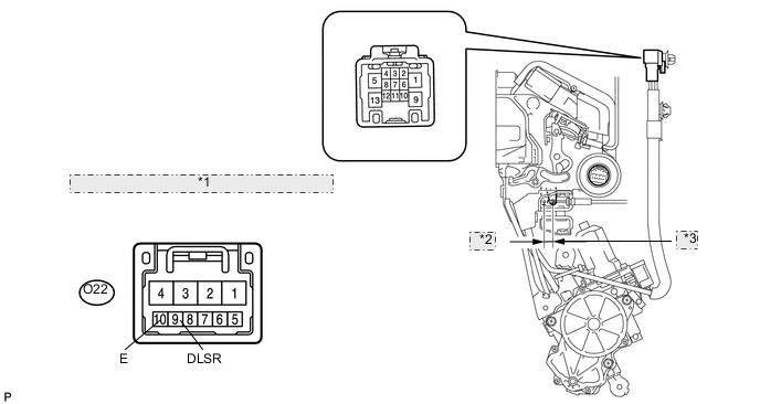
INSPECT REAR DOOR LOCK ASSEMBLY LH (DOUBLE DOOR LOCK MOTOR)

*1 Component without harness connected: (Rear Door Lock LH) *2 Lock *3 Unlock
-
Check operation of the double lock motor.
-
Apply battery voltage to the door lock and set the door lock motor to the lock position.
OK Measurement Condition Specified Condition Battery positive (+) → Terminal O22-2 (L)
Battery negative (-) → Terminal O22-1 (UL)
Lock -
Apply battery voltage to the door lock motor and check the operation of the double door lock motor.
OK Measurement Condition Specified Condition Battery positive (+) → Terminal O22-4 (DL)
Battery negative (-) → Terminal O22-3 (UNDL)
Set Battery positive (+) → Terminal O22-3 (UNDL)
Battery negative (-) → Terminal O22-4 (DL)
Unset -
While the double locking system is set, check that the doors cannot be unlocked by operating the control cable.
-
NG
REPLACE REAR DOOR LOCK ASSEMBLY LH Click here
OK
-
-
READ VALUE USING INTELLIGENT TESTER (DOUBLE DOOR LOCK POSITION SWITCH)
-
Use the Data List to check if the double door lock position switch is functioning properly.
Rear Left Door (Rear door ECU LH) Tester Display Measurement Item/Display (Range) Normal Condition Diagnostic Note Double Lock Position SW Rear LH side double door lock position switch signal / ON or OFF ON: Rear LH side double door lock is unset
OFF: Rear LH side double door lock is set
- OK ON (rear LH side double door lock is unset) appears on screen.
OK
REPLACE REAR DOOR ECU LH Click here
NG
-
-
INSPECT REAR DOOR LOCK ASSEMBLY LH (DOUBLE DOOR LOCK POSITION SWITCH)
*1 Component without harness connected: (Rear Door Lock LH) *2 Lock *3 Unlock
-
Measure the resistance according to the value(s) in the table below.
Standard resistance Tester Connection Switch Condition Specified Condition O22-9 (DLSR) - O22-10 (E) Set Below 1 Ω O22-9 (DLSR) - O22-10 (E) Unset 10 kΩ or higher
NG
REPLACE REAR DOOR LOCK ASSEMBLY LH Click here
OK
-
-
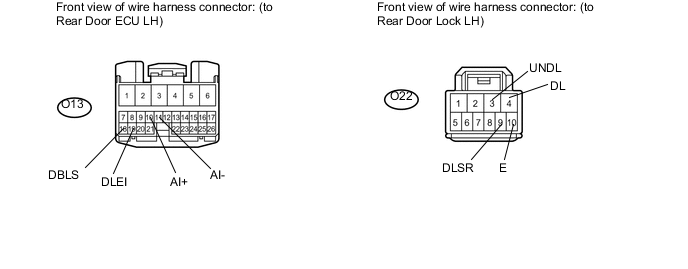
CHECK HARNESS AND CONNECTOR (REAR DOOR LOCK LH - REAR DOOR ECU LH)
-
Disconnect the O13 ECU connector.
-
Disconnect the O22 door lock connector.
-
Measure the resistance according to the value(s) in the table below.
Standard resistance Tester Connection Condition Specified Condition O13-10 (AI+) - O22-4 (DL) Always Below 1 Ω O13-11 (AI-) - O22-3 (UNDL) Always Below 1 Ω O13-18 (DBLS) - O22-9 (DLSR) Always Below 1 Ω O13-19 (DBEI) - O22-10 (E) Always Below 1 Ω O13-10 (AI+) - Body ground Always 10 kΩ or higher O13-11 (AI-) - Body ground Always 10 kΩ or higher O13-18 (DBLS) - Body ground Always 10 kΩ or higher O13-19 (DBEI) - Body ground Always 10 kΩ or higher
OK
REPLACE REAR DOOR ECU LH Click here
NG
REPAIR OR REPLACE HARNESS OR CONNECTOR
-
-
INSPECT REAR DOOR LOCK ASSEMBLY RH (DOUBLE DOOR LOCK MOTOR)
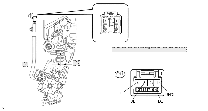
*1 Component without harness connected: (Rear Door Lock RH) *2 Unlock *3 Lock
-
Check operation of the double lock motor.
-
Apply battery voltage to the door lock and set the door lock motor to the lock position.
OK Measurement Condition Specified Condition Battery positive (+) → Terminal O11-4 (L)
Battery negative (-) → Terminal O11-3 (UL)
Lock -
Apply battery voltage to the door lock motor and check the operation of the double door lock motor.
OK Measurement Condition Specified Condition Battery positive (+) → Terminal O11-2 (DL)
Battery negative (-) → Terminal O11-1 (UNDL)
Set Battery positive (+) → Terminal O11-1 (UNDL)
Battery negative (-) → Terminal O11-2 (DL)
Unset -
While the double locking system is set, check that the doors cannot be unlocked by operating the control cable.
-
NG
REPLACE REAR DOOR LOCK ASSEMBLY RH Click here
OK
-
-
READ VALUE USING INTELLIGENT TESTER (DOUBLE DOOR LOCK POSITION SWITCH)
-
Use the Data List to check if the double door lock position switch is functioning properly.
Rear Right Door (Rear door ECU RH) Tester Display Measurement Item/Display (Range) Normal Condition Diagnostic Note Double Lock Position SW Rear RH side double door lock position switch signal/ON or OFF ON: Rear RH side double door lock is unset
OFF: Rear RH side double door lock is set
- OK ON (rear RH side double door lock is unset) appears on screen.
OK
REPLACE REAR DOOR ECU RH Click here
NG
-
-
INSPECT REAR DOOR LOCK ASSEMBLY RH (DOUBLE DOOR LOCK POSITION SWITCH)
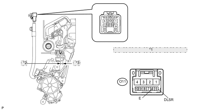
*1 Component without harness connected: (Rear Door Lock RH) *2 Unlock *3 Lock
-
Measure the resistance according to the value(s) in the table below.
Standard resistance Tester Connection Switch Condition Specified Condition O11-5 (DLSR) - O11-6 (E) Set Below 1 Ω O11-5 (DLSR) - O11-6 (E) Unset 10 kΩ or higher
NG
REPLACE REAR DOOR LOCK ASSEMBLY RH Click here
OK
-
-
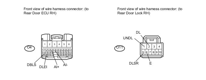
CHECK WIRE HARNESS (REAR DOOR LOCK RH - REAR DOOR ECU RH)
-
Disconnect the O4 ECU connector.
-
Disconnect the O11 door lock connector.
-
Measure the resistance according to the value(s) in the table below.
Standard resistance Tester Connection Condition Specified Condition O4-10 (AI+) - O11-2 (DL) Always Below 1 Ω O4-11 (AI-) - O11-1 (UNDL) Always Below 1 Ω O4-18 (DBLS) - O11-5 (DLSR) Always Below 1 Ω O4-19 (DBEI) - O11-6 (E) Always Below 1 Ω O4-10 (AI+) - Body ground Always 10 kΩ or higher O4-11 (AI-) - Body ground Always 10 kΩ or higher O4-18 (DBSLI - Body ground Always 10 kΩ or higher O4-19 (DBEI) - Body ground Always 10 kΩ or higher
OK
REPLACE REAR DOOR ECU RH Click here
NG
REPAIR OR REPLACE HARNESS OR CONNECTOR
-