WIRELESS DOOR LOCK CONTROL SYSTEM No Answer-Back
DESCRIPTION
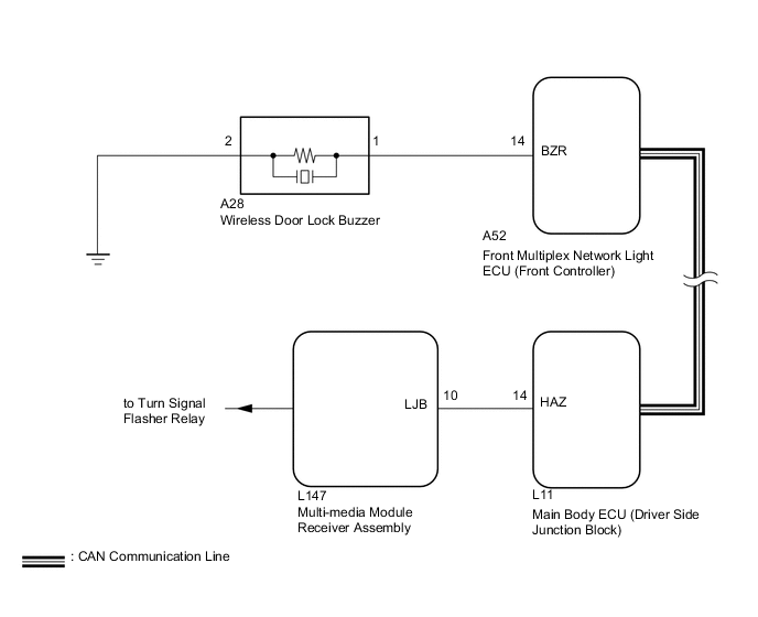
In some cases, wireless door lock control functions are normal but the turn signal lights and wireless door lock buzzer* are not. Malfunctions may be present in the main body ECU, turn signal lights and wireless door lock buzzer signal outputs*.
-
*: For Europe and China, there is no buzzer sound answer-back function.
Note
-
Before performing the inspection, check that there are no problems related to the "CAN COMMUNICATION SYSTEM".
-
When troubleshooting a function, first make sure that the answer-back functions are set to the default setting.
-
Check that DTC B1242 is not output.
WIRING DIAGRAM
PROCEDURE
-
READ VALUE USING INTELLIGENT TESTER (LOCK POSITION SWITCH)
-
Using the intelligent tester, read the Data List.
Driver Door Tester Display Measurement Item/Display Normal Condition Diagnostic Note Lock position switch Driver side door lock position switch signal / ON or OFF ON: Driver side door is unlocked
OFF: Driver side door is locked
- Passenger Door Tester Display Measurement Item/Display Normal Condition Diagnostic Note Lock position switch Passenger side door lock position switch signal / ON or OFF ON: Passenger side door is unlocked
OFF: Passenger side door is locked
- Rear Left Door Tester Display Measurement Item/Display Normal Condition Diagnostic Note Lock position switch Rear door LH lock position switch signal / ON or OFF ON: Rear door LH is unlocked
OFF: Rear door LH is locked
- Rear Right Door Tester Display Measurement Item/Display Normal Condition Diagnostic Note Lock position switch Rear door RH lock position switch signal / ON or OFF ON: Rear door RH is unlocked
OFF: Rear door RH is locked
- OK On tester screen, item changes between ON and OFF according to above chart. Result Result Proceed to OK A NG (for Driver Side) B NG (for Passenger Side) C NG (for Rear LH Side) D NG (for Rear RH Side) E
B 
Go to POWER DOOR LOCK CONTROL SYSTEM (Proceed to Only Driver Door LOCK/UNLOCK Functions do not Operate) Click here
C
Go to POWER DOOR LOCK CONTROL SYSTEM (Proceed to Only Passenger Door LOCK/UNLOCK Functions do not Operate) Click here
D
Go to POWER DOOR LOCK CONTROL SYSTEM (Proceed to Only Rear Door LH LOCK/UNLOCK Functions do not Operate) Click here
E
Go to POWER DOOR LOCK CONTROL SYSTEM (Proceed to Only Rear Door RH LOCK/UNLOCK Functions do not Operate) Click here
A 
-
-
CHECK WIRELESS DOOR LOCK FUNCTION
-
Check that the wireless door lock control functions operate with a transmitter Click here.
Result: Result Proceed to Wireless door lock control functions operate normally but turn signal light answer-back does not occur A Wireless door lock control functions operate normally but wireless door lock buzzer answer-back does not occur B Wireless door lock control functions do not operate C
B 
CHECK HARNESS AND CONNECTOR (FRONT MULTIPLEX NETWORK LIGHT ECU - WIRELESS DOOR LOCK BUZZER AND BODY GROUND) Click here
C
Go to "Only Wireless Control Function is Inoperative" Click here
A
-
-
CHECK HAZARD WARNING LIGHT
-
Check that the turn signal lights flash continuously when the hazard warning signal switch is pressed.
OK Hazard warning lights flash continuously.
NG
Go to LIGHTING SYSTEM Click here
OK
-
-
PERFORM ACTIVE TEST USING INTELLIGENT TESTER (HAZARD)
-
Operate the intelligent tester according to the steps on the display and select "Active Test".
Main Body Item Test Part Control Range Hazard Turn signal flasher relay ON or OFF OK Hazard warning lights condition can be switched by "Active Test".
OK
REPLACE MAIN BODY ECU (DRIVER SIDE JUNCTION BLOCK)
NG
CHECK HARNESS AND CONNECTOR (MAIN BODY ECU - MULTI-MEDIA MODULE RECEIVER ASSEMBLY) Click here
-
-
CHECK HARNESS AND CONNECTOR (FRONT MULTIPLEX NETWORK LIGHT ECU - WIRELESS DOOR LOCK BUZZER AND BODY GROUND)
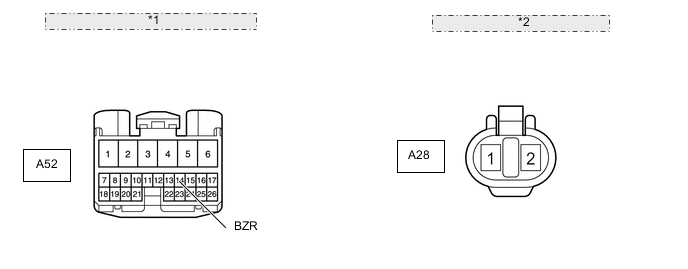
*1 Front view of wire harness: (to Front Multiplex Network Light ECU) *2 Front view of wire harness: (to Wireless Door Lock Buzzer)
-
Disconnect the A52 ECU connector.
-
Disconnect the A28 buzzer connector.
-
Measure the resistance according to the value(s) in the table below.
Standard resistance Tester Connection Condition Specified Condition A52-14 (BZR) - A28-1 Always Below 1 Ω A28-2 - Body ground A52-14 (BZR) - A28-1 - Body ground Always 10 kΩ or higher
NG
REPAIR OR REPLACE HARNESS OR CONNECTOR
OK
-
-
CHECK WIRELESS DOOR LOCK BUZZER (OPERATION)
-
Temporarily replace the wireless door lock buzzer with a new one Click here.
-
Check that the wireless door lock buzzer sounds by using the transmitter LOCK/UNLOCK switch.
OK Wireless door lock buzzer sounds.
OK
END (WIRELESS DOOR LOCK BUZZER IS DEFECTIVE)
NG
-
-
CHECK FRONT MULTIPLEX NETWORK LIGHT ECU (OPERATION)
-
Temporarily replace the front multiplex network light ECU with a new one.
-
Check that the wireless door lock buzzer sounds by using transmitter LOCK/UNLOCK switch.
OK Wireless door lock buzzer sounds.
OK
END (FRONT MULTIPLEX NETWORK LIGHT ECU IS DEFECTIVE)
NG
REPLACE MAIN BODY ECU (DRIVER SIDE JUNCTION BLOCK)
-
-
CHECK HARNESS AND CONNECTOR (MAIN BODY ECU - MULTI-MEDIA MODULE RECEIVER ASSEMBLY)
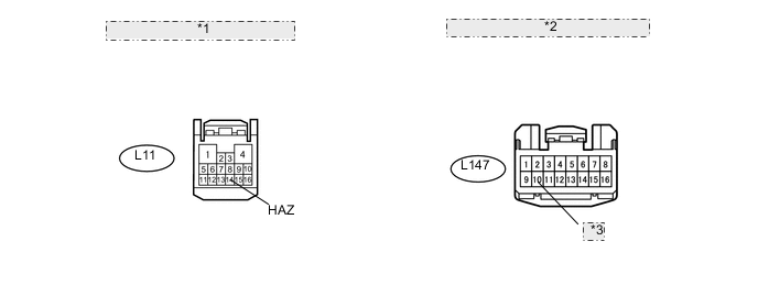
*1 Front view of wire harness: (to Main Body ECU) *2 Front view of wire harness: (to Multi-media Module Receiver Assembly) *3 LJB
-
Disconnect the L11 ECU connector.
-
Disconnect the L147 receiver connector.
-
Measure the resistance according to the value(s) in the table below.
Standard resistance Tester Connection Condition Specified Condition L11-14 (HAZ) - L147-10 (LJB) Always Below 1 Ω L11-14 (HAZ) or L147-10 (LJB) - Body ground Always 10 kΩ or higher
NG
REPAIR OR REPLACE HARNESS OR CONNECTOR
OK
-
-
CHECK MULTI-MEDIA MODULE RECEIVER ASSEMBLY (OPERATION)
-
Temporarily replace the multi-media module receiver assembly with a new one Click here.
-
Check that the hazard warning lights flash continuously by using transmitter LOCK/UNLOCK switch.
OK Hazard warning lights flash continuously.
OK
END (MULTI-MEDIA MODULE RECEIVER ASSEMBLY IS DEFECTIVE)
NG
REPLACE MAIN BODY ECU (DRIVER SIDE JUNCTION BLOCK)
-