WIPER AND WASHER SYSTEM Headlight Cleaner Switch Circuit
DESCRIPTION
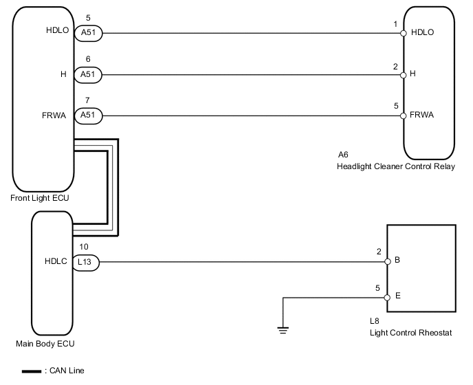
This circuit detects the conditions of the headlight control rheostat.
The headlight cleaner control relay receives the following signals through the CAN line:
-
Headlight control rheostat signal
-
Headlight operating signal
-
Daytime running light operating signal
-
Front washer motor operating signal
WIRING DIAGRAM
PROCEDURE
-
CHECK FRONT LIGHT ECU (HDLO SIGNAL)
-
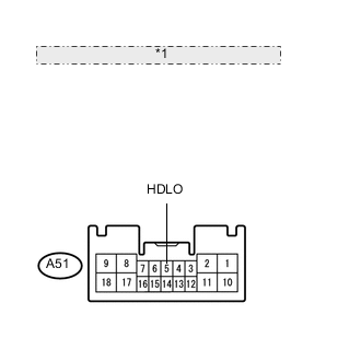
*1 Rear view of wire harness connector: (to Front Light ECU) Measure the voltage according to the value(s) in the table below.
Standard voltage Tester Connection Switch Condition Specified Condition A51-5 (HDLO) - Body ground Engine switch on (IG), light control rheostat OFF 11 to 14 V A51-5 (HDLO) - Body ground Engine switch on (IG), light control rheostat in HEAD or TAIL Below 1 V
NG 
CHECK HARNESS AND CONNECTOR (CONTROL RELAY - FRONT LIGHT ECU) Click here
OK 
-
-
CHECK FRONT LIGHT ECU (FRWA SIGNAL)
-
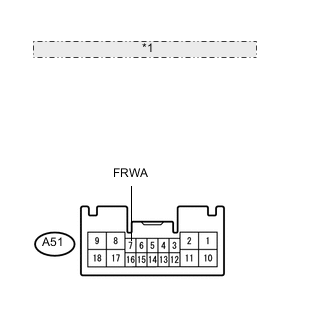
*1 Rear view of wire harness connector: (to Front Light ECU) Measure the voltage according to the value(s) in the table below.
Standard voltage Tester Connection Switch Condition Specified Condition A51-7 (FRWA) - Body ground Engine switch on (IG), front washer is stopped 10 to 14 V A51-7 (FRWA) - Body ground Engine switch on (IG), front washer is operated Below 1 V
NG
CHECK HARNESS AND CONNECTOR (CONTROL RELAY - FRONT LIGHT ECU) Click here
OK
-
-
CHECK HARNESS AND CONNECTOR (RHEOSTAT - BODY GROUND)
-
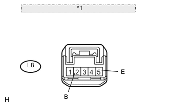
*1 Front view of wire harness connector: (to Rheostat) Disconnect the L8 rheostat connector.
-
Measure the voltage according to the value(s) in the table below.
Standard voltage Tester Connection Condition Specified Condition L8-2 (B) - Body ground Always 11 to 14 V -
Measure the resistance according to the value(s) in the table below.
Standard resistance Tester Connection Condition Specified Condition L8-5 (E) - Body ground Below Always Below 1 Ω
NG 
REPAIR OR REPLACE HARNESS OR CONNECTOR
OK
-
-
CHECK HEADLIGHT CLEANER CONTROL RELAY
-
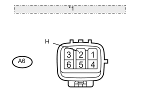
*1 Front view of wire harness connector: (to Control Relay) Disconnect the A6 control relay connector.
-
Measure the voltage according to the value(s) in the table below.
Standard voltage Tester Connection Condition Specified Condition A6-2 (H) - Body ground Always 11 to 14 V
OK
PROCEED TO NEXT CIRCUIT INSPECTION SHOWN IN PROBLEM SYMPTOMS TABLE Click here
NG
CHECK HARNESS AND CONNECTOR (CONTROL RELAY - FRONT LIGHT ECU) Click here
-
-
CHECK HARNESS AND CONNECTOR (CONTROL RELAY - FRONT LIGHT ECU)
-
Disconnect the A6 control relay connector.
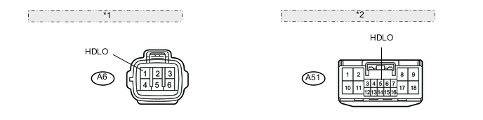
*1 Front view of wire harness connector: (to Control Relay) *2 Front view of wire harness connector: (to Front Light ECU) -
Disconnect the A51 ECU connector.
-
Measure the resistance according to the value(s) in the table below.
Standard resistance Tester Connection Condition Specified Condition A6-1 (HDLO) - A51-5 (HDLO) Always Below 1 Ω A6-1 (HDLO) - Body ground Always 10 kΩ or higher
OK
PROCEED TO NEXT CIRCUIT INSPECTION SHOWN IN PROBLEM SYMPTOMS TABLE Click here
NG
REPAIR OR REPLACE HARNESS OR CONNECTOR
-
-
CHECK HARNESS AND CONNECTOR (CONTROL RELAY - FRONT LIGHT ECU)
-
Disconnect the A6 control relay connector.
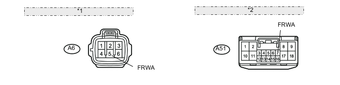
*1 Front view of wire harness connector: (to Control Relay) *2 Front view of wire harness connector: (to Front Light ECU) -
Disconnect the A51 ECU connector.
-
Measure the resistance according to the value(s) in the table below.
Standard resistance Tester Connection Condition Specified Condition A6-5 (FRWA) - A51-7 (FRWA) Always Below 1 Ω A6-5 (FRWA) - Body ground Always 10 kΩ or higher
OK
PROCEED TO NEXT CIRCUIT INSPECTION SHOWN IN PROBLEM SYMPTOMS TABLE Click here
NG
REPAIR OR REPLACE HARNESS OR CONNECTOR
-
-
CHECK HARNESS AND CONNECTOR (CONTROL RELAY - FRONT LIGHT ECU)
-
Disconnect the A6 control relay connector.
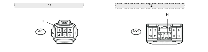
*1 Front view of wire harness connector: (to Headlight Cleaner Control Relay) *2 Front view of wire harness connector: (to Front Controller) -
Disconnect the A51 ECU connector.
-
Measure the resistance according to the value(s) in the table below.
Standard resistance Tester Connection Condition Specified Condition A6-2 (H) - A51-6 (H) Always Below 1 Ω A6-2 (H) - Body ground Always 10 kΩ or higher
OK
PROCEED TO NEXT CIRCUIT INSPECTION SHOWN IN PROBLEM SYMPTOMS TABLE Click here
NG
REPAIR OR REPLACE HARNESS OR CONNECTOR
-