WIPER AND WASHER SYSTEM Wiper Switch (HI Speed) Circuit
DESCRIPTION
The front light ECU receives the HI position signal of the wiper switch to operate the wiper motor at HI speed. Even if the ECU malfunctions, its circuit structure enables it to operate the wiper in HI operation mode.
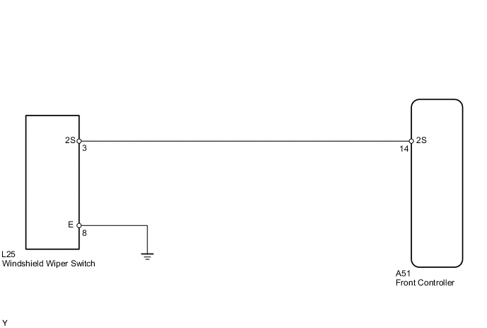
WIRING DIAGRAM
PROCEDURE
-
CHECK FRONT LIGHT ECU (2S SIGNAL)
-
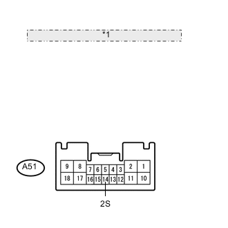
*1 Front view of wire harness connector: (to Front Light ECU) Measure the voltage according to the value(s) in the table below.
Standard voltage Tester Connection Switch Condition Specified Condition A51-14 (2S) - Body ground Wiper switch not in HI position 11 to 14 V A51-14 (2S) - Body ground Wiper switch in HI position Below 1 V
OK 
PROCEED TO NEXT CIRCUIT INSPECTION SHOWN IN PROBLEM SYMPTOMS TABLE Click here
NG 
-
-
INSPECT WINDSHIELD WIPER SWITCH (COMBINATION SWITCH ECU)
-
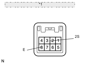
*1 Component with harness connected: (Windshield Wiper Switch) Disconnect or remove switch Click here
-
Measure the resistance according to the value(s) in the table below.
Standard resistance Tester Connection Switch Condition Specified Condition 3 (2S) - 8 (E) Wiper switch in HI position Below 1 Ω 3 (2S) - 8 (E) Wiper switch not in HI position 10 kΩ or higher
NG
REPLACE WINDSHIELD WIPER SWITCH Click here
OK
-
-
CHECK HARNESS AND CONNECTOR (WIPER SWITCH - LIGHT ECU AND BODY GROUND)
-
Disconnect the L25 switch connector.
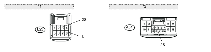
*1 Front view of wire harness connector: (to Wiper Switch) *2 Front view of wire harness connector: (to Front Light ECU) -
Disconnect the A51 ECU connector.
-
Measure the resistance according to the value(s) in the table below.
Standard resistance Tester Connection Condition Specified Condition L25-3 (2S) - A51-14 (2S) Always Below 1 Ω L25-8 (E) - Body ground Always Below 1 Ω A51-14 (2S) - Body ground Always 10 kΩ or higher
OK
PROCEED TO NEXT CIRCUIT INSPECTION SHOWN IN PROBLEM SYMPTOMS TABLE Click here
NG
REPAIR OR REPLACE HARNESS OR CONNECTOR
-