WIPER AND WASHER SYSTEM, Diagnostic DTC:B1400
| DTC Code | DTC Name |
|---|---|
| B1400 | Rain Sensor Malfunction |
DESCRIPTION
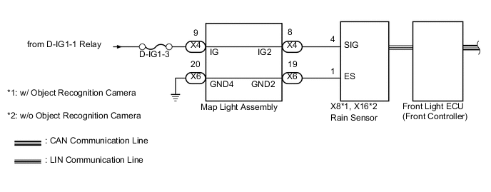
When the windshield wiper switch assembly position is set to AUTO, the rain sensor detects the amount of raindrops. According to the amount of raindrops, the rain sensor sends wiper drive request signals to the front light ECU (front controller) at the optimal timings via LIN communication. Also, the vehicle speed-sensitive intermittent operation is still performed even when there is a rain sensor malfunction.
| DTC Code | DTC Detection Condition | Trouble Area |
|---|---|---|
| B1400 |
|
|
WIRING DIAGRAM
CAUTION / NOTICE / HINT
Note
-
Inspect the fuses for circuits related to this system before performing the following inspection procedure.
-
Since the wiper and washer system has functions that use LIN communication and CAN communication, first confirm that there is no malfunction in the communication system by inspecting the LIN communication functions and CAN communication in accordance with the "How to Proceed with Troubleshooting" procedures. Then, conduct the following inspection procedure.
PROCEDURE
-
READ VALUE USING INTELLIGENT TESTER
-
Check the Data List for proper functioning of the rain sensor.
Rain Sensor Tester Display Measurement Item/Range Normal Condition Diagnostic Note Sensor Low Temp Info Rain sensor low temp / NG or OK NG: Rain sensor is low temp
OK: Rain sensor is normal
- Sensor High Temp Info Rain sensor high temp / NG or OK NG: Rain sensor is high temp
OK: Rain sensor is normal
- OK The display is as specified in the normal condition.
NG 
REPLACE RAIN SENSOR Click here
OK 
-
-
INSPECT MAP LIGHT ASSEMBLY
-
Remove the map light Click here.
-
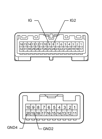
Measure the resistance according to the value(s) in the table below.
Standard Resistance Tester Connection Condition Specified Condition 19 (GND2) - 20 (GND4) Always Below 1 Ω 8 (IG2) - 9 (IG) Always Below 1 Ω
NG
REPLACE MAP LIGHT ASSEMBLY Click here
OK
-
-
CHECK HARNESS AND CONNECTOR (MAP LIGHT ASSEMBLY - BATTERY AND BODY GROUND)
-
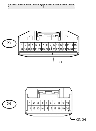
*1 Front view of wire harness connector: (to Map Light) Disconnect the X4 and X6 map light connectors.
-
Measure the resistance according to the value(s) in the table below.
Standard Resistance Tester Connection Condition Specified Condition X6-20 (GND4) - Body ground Always Below 1 Ω -
Measure the voltage according to the value(s) in the table below.
Standard Voltage Tester Connection Switch Condition Specified Condition X4-9 (IG) - Body ground Engine switch on (IG) 11 to 14 V X4-9 (IG) - Body ground Engine switch off Below 1 V
NG
REPAIR OR REPLACE HARNESS OR CONNECTOR
OK
-
-
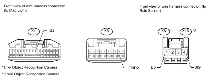
CHECK HARNESS AND CONNECTOR (MAP LIGHT ASSEMBLY - RAIN SENSOR)
-
Disconnect the X4 and X6 map light connectors.
-
Disconnect the X8*1 or X16*2 rain sensor connector.
-
*1: w/ Object Recognition Camera
-
*2: w/o Object Recognition Camera
-
-
Measure the resistance according to the value(s) in the table below.
Standard Resistance w/ Object Recognition Camera Tester Connection Condition Specified Condition X6-19 (GND2) - X8-1 (ES) Always Below 1 Ω X4-8 (IG2) - X8-4 (SIG) X6-19 (GND2) - Body ground Always 10 kΩ or higher X4-8 (IG2) - Body ground Standard Resistance w/o Object Recognition Camera Tester Connection Condition Specified Condition X6-19 (GND2) - X16-1 (ES) Always Below 1 Ω X4-8 (IG2) - X16-4 (SIG) X6-19 (GND2) - Body ground Always 10 kΩ or higher X4-8 (IG2) - Body ground
OK
REPLACE RAIN SENSOR Click here
NG
REPAIR OR REPLACE HARNESS OR CONNECTOR
-