WIPER AND WASHER SYSTEM TERMINALS OF ECU
-
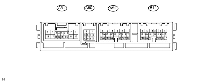
CHECK FRONT LIGHT ECU (FRONT CONTROLLER)
-
Disconnect the A50 and A52 ECU connectors.
-
Measure the voltage and resistance according to the value(s) in the table below.
Terminal No. (Symbols) Wiring Color Terminal Description Condition Specified Condition A52-1 (BATB) - A50-2 (E) P - W-B Power source Always 11 to 14 V A52-5 (ALTB) - A50-2 (E) L - W-B Power source Always 11 to 14 V A50-1 (FMB3) - A50-2 (E) LG - W-B Power source Always 11 to 14 V A50-2 (E) - Body ground W-B - Body ground Power ground Always Below 1 Ω A50-5 (FMIG) - A50-2 (E) Y - W-B Power source Engine switch on (IG) 11 to 14 V If the result is not as specified, there may be a malfunction on the wire harness side.
-
Reconnect the A50 and A52 ECU connectors.
-
Measure the voltage and resistance according to the value(s) in the table below.
Terminal No. (Symbols) Wiring Color Terminal Description Condition Specified Condition A51-1 (S/M) - Body ground B - Body ground Front wiper motor operation signal Front wiper is operated 10 to 14 V Front wiper is stopped Below 1 V A51-2 (WIG) - Body ground L - Body ground Front wiper motor power source circuit Engine switch off Below 1 V Engine switch on (IG) 11 to 14 V A51-8 (S/S) - Body ground P - Body ground Front wiper motor power supply circuit Front wiper switch off Below 1 V Front wiper switch low 11 to 14 V A51-9 (+2) - Body ground L - Body ground Front wiper motor power supply circuit (HI signal) Front wiper switch off Below 1 V Front wiper switch hi 11 to 14 V A51-14 (2S) - Body ground R - Body ground Front wiper switch HI signal (to combination switch) Front wiper switch off Below 1 V Front wiper switch hi 11 to 14 V A51-17 (W+) - Body ground B - Body ground Power source circuit (from battery) Always 11 to 14 V If the result is not as specified, the ECU may have a malfunction.
-
-
CHECK WINDSHIELD WIPER SWITCH

-
Disconnect the L25 switch connectors.
-
Measure the voltage according to the value(s) in the table below.
Terminal No. (Symbols) Wiring Color Terminal Description Condition Specified Condition L25-1 (B) - L25-8 (E) B - W-B Power source circuit (from battery) Always 11 to 14 V L25-2 (IG) - L25-8 (E) G - W-B IG signal circuit Engine switch off Below 1 V Engine switch on (IG) 11 to 14 V L25-3 (2S) - Body ground R - Body ground Wiper switch HI signal Front wiper switch off Below 1 V Front wiper switch hi 11 to 14 V L25-8 (E) - Body ground W-B - Body ground Ground circuit Always Below 1 V If the result is not as specified, there may be a malfunction on the wire harness side.
-
-
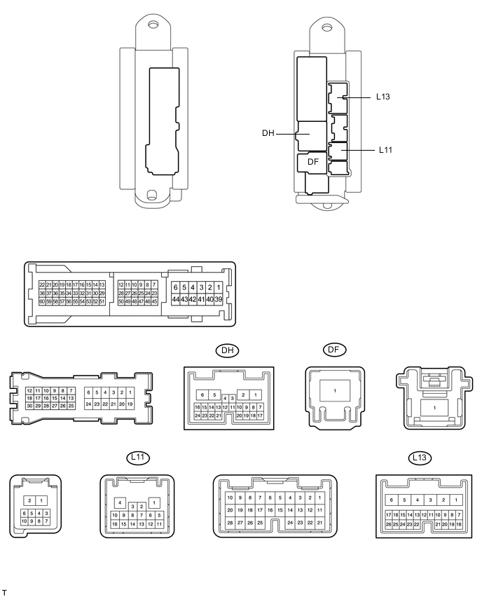
CHECK MAIN BODY ECU
-
Disconnect the L11, L13, DF and DH main body ECU connectors.
-
Measure the voltage according to the value(s) in the table below.
Terminal No. (Symbols) Wiring Color Terminal Description Condition Specified Condition L13-6 (AM1) - L11-1 (GND3) GR - W-B ECU power supply (from battery) Always 11 to 14 V DF-1 (IG) - L11-1 (GND3) GR - W-B IG signal circuit Engine switch off Below 1 V Engine switch on (IG) 11 to 14 V DH-23 (STP) - L11-1 (GND3) L - W-B Stop light switch circuit Stop light switch off Below 1 V Stop light switch on 11 to 14 V L11-1 (GND3) - Body ground W-B Body ground Ground circuit Always Below 1 V If the result is not as specified, there may be a malfunction on the wire harness side.
-
-
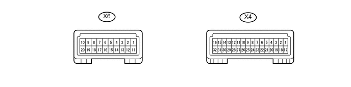
CHECK MAP LIGHT
-
Disconnect the X4 and X6 map light connectors.
-
Measure the voltage according to the value(s) in the table below.
Terminal No. (Symbols) Wiring Color Terminal Description Condition Specified Condition X4-6 (+B) - Body ground B - Body ground ECU power supply (from battery) Always 11 to 14 V X4-9 (IG) - Body ground L - Body ground IG signal circuit Engine switch off Below 1 V Engine switch on (IG) 11 to 14 V X6-19 (GND2) - Body ground B - Body ground Ground circuit Always Below 1 V If the result is not as specified, there may be a malfunction on the wire harness side.
-
-
CHECK RAIN SENSOR

-
Disconnect the X8 rein sensor connectors.
-
Measure the voltage according to the value(s) in the table below.
Terminal No. (Symbols) Wiring Color Terminal Description Condition Specified Condition X8-4 (SIG) - Body ground LG - Body ground IG signal circuit (to IG relay) Engine switch off Below 1 V Engine switch on (IG) 11 to 14 V X8-1 (ES) - Body ground BR - Body ground Ground circuit Always Below 1 V If the result is not as specified, there may be a malfunction on the wire harness side.
-
-
CHECK HEADLIGHT CLEANER CONTROL RELAY

-
Disconnect the A6 relay connectors.
-
Measure the voltage according to the value(s) in the table below.
Terminal No. (Symbols) Wiring Color Terminal Description Condition Specified Condition A6-3 (IG) - A6-4 (E) Y - W-B IG signal circuit (to IG relay) Engine switch off Below 1 V Engine switch on (IG) 11 to 14 V A6-6 (PB) - A6-4 (E) R-B - W-B Headlight cleaner motor operation signal Headlight cleaner motor is stopped Below 1 V Headlight cleaner motor is operating 11 to 14 V If the result is not as specified, there may be a malfunction on the wire harness side.
-
Reconnect the A6 relay connectors.
-
Measure the voltage and resistance according to the value(s) in the table below.
Terminal No. (Symbols) Wiring Color Terminal Description Condition Specified Condition A6-1 ((HDLO) - A6-4 (E) L - W-B Daytime running light system operation signal Daytime running light is not operating Below 1 V Daytime running light is operating 11 to 14 V A6-2 (H) - A6-4 (E) B - W-B Headlight cleaner switch operation signal Headlight cleaner switch is off Below 1 V Headlight cleaner switch is on 11 to 14 V A6-5 (FRWA) - A6-4 (E) R - W-B Front washer motor operation signal Front washer switch is off Below 1 V Front washer switch is on 11 to 14 V If the result is not as specified, the ECU may have a malfunction.
-