HEADLIGHT ASSEMBLY(for LED Headlight) REASSEMBLY
CAUTION / NOTICE / HINT
Tech Tips
-
Use the same procedure for the RH side and LH side.
-
The procedure listed below is for the LH side.
PROCEDURE
-
INSTALL CLEARANCE LIGHT UNIT LH
-
Install the clearance light unit LH with the 3 screws.
-
-
INSTALL FRONT TURN SIGNAL LIGHT UNIT LH
Note
-
Wear rubber gloves when installing the front turn signal light unit LH in order to protect your hands, prevent fingerprints and to keep the lens free from foreign matter. Do not use cotton gloves.
-
Do not touch the front turn signal light unit LH with bare hands.
-
If there are fingerprints on the front turn signal light unit LH, wipe them off with a soft cloth.
-
Do not allow dirt or foreign matter on the front turn signal light unit LH.
-
Install the front turn signal light unit with the 2 screws.
-
Attach the clamp.
-
Install the cover with the 2 screws.
-
Install the light unit with the 4 screws.
-
Attach the clamp.
-
Install the plate with the 2 screws.
-
-
INSTALL LIGHT CONTROL ECU (w/o Driver Monitor Camera)
-
Connect the connector.
-
Install the light control ECU with the 2 screws.
-
-
INSTALL LIGHT CONTROL ECU
-
Connect the connector.
-
Install the light control ECU with the 2 screws.
-
-
INSTALL HEADLIGHT SHADE ECU (w/ Adaptive High Beam System)
-
Connect the connector.
-
Install the headlight shade ECU with the 2 screws.
-
-
INSTALL HEADLIGHT UNIT ASSEMBLY LH (w/o Driver Monitor Camera)
-
Push the headlight unit assembly LH into the 2 aiming screws from the front, and turn the 2 aiming screws clockwise.
Note
-
Wear rubber gloves when installing the headlight unit assembly LH in order to protect your hands, prevent fingerprints and to keep the lens free from foreign matter. Do not use cotton gloves.
-
Do not touch the headlight unit assembly LH with bare hands.
-
If there are fingerprints on the headlight unit assembly LH, wipe them off with a soft cloth.
-
Do not allow dirt or foreign matter on the headlight unit assembly LH.
-
-
Turn the 2 aiming screws so that the dimension is the same as measured before removing.
-
Attach the 2 claws to install the headlight unit assembly LH.
-
Install the connected gears to the aiming screw with the 3 screws.
-
-
INSTALL HEADLIGHT SWIVEL MOTOR LH
-
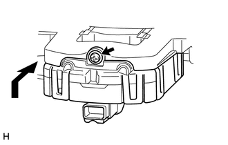
Move the headlight swivel motor LH as shown in the illustration to install it to the headlight LED unit assembly LH.
-
Install the screw.
-
-
INSTALL HEADLIGHT LED UNIT ASSEMBLY LH
-
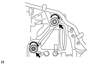
Push the headlight LED unit assembly LH into the 2 aiming screws from the front, and turn the 2 aiming screws clockwise.
Note
-
Wear rubber gloves when installing the headlight LED unit assembly LH in order to protect your hands, prevent fingerprints and to keep the lens free from foreign matter. Do not use cotton gloves.
-
Do not touch the headlight LED unit assembly LH with bare hands.
-
If there are fingerprints on the headlight LED unit assembly LH, wipe them off with a soft cloth.
-
Do not allow dirt or foreign matter on the headlight LED unit assembly LH.
-
-
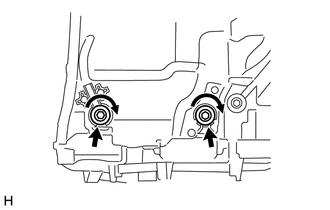
Turn the 2 aiming screws so that the dimension is the same as measured before removing.
-
Attach the 2 claws to install the HID unit.
-
Connect the 2 connectors.
-
Detach the claw to install the plate.
-
Install the connected gears to the aiming screw with the 4 screws.
-
Connect the connectors.
-
Install the light unit with the 5 screws.
Note
-
Wear rubber gloves when installing the light unit in order to protect your hands, prevent fingerprints and to keep the lens free from foreign matter. Do not use cotton gloves.
-
Do not touch the light unit with bare hands.
-
If there are fingerprints on the light unit, wipe them off with a soft cloth.
-
Do not allow dirt or foreign matter on the light unit.
-
-
-
INSTALL HEADLIGHT LENS GASKET
-
Completely remove the old headlight lens gasket.
-
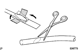
Partially remove the peeling paper, and cut off a piece of it.
-
Fold the peeling paper over the tip of a screwdriver and fix it in place with tape.
Note
Use the peeling paper that is supplied with the seal.
-
Using scissors, cut the end of the seal at a diagonal (45°).
-
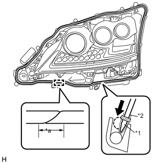
Set the seal into the groove so that the ends of the seal are aligned with the bottom of the headlight as shown in the illustration.
-
Using the screwdriver, completely press the seal into the headlight to install the seal.
-
After pressing the seal completely, cut the seal ends at a diagonal (45°) so that the ends overlap for 10 mm (0.394 in.) or more.
Text in Illustration *1 Peeling Paper *2 Tape *a 10 mm (0.394 in.)
-
-
INSTALL HEADLIGHT LENS LH
-
Attach the 7 claws to install the headlight lens LH.
Note
-
Wear rubber gloves when installing the fog light lens LH in order to protect your hands, prevent fingerprints and to keep the lens free from foreign matter. Do not use cotton gloves.
-
Do not touch the rear side of the fog light lens LH or the aluminum surfaces of the LED unit with bare hands.
-
If there are fingerprints on the aluminum surfaces of the LED unit, etc., wipe them off with a soft cloth.
-
If there are fingerprints on the back of the lens, replace the headlight lens LH.
-
Do not allow dirt or foreign matter on the rear side of the fog light lens LH or aluminum surfaces of the LED unit.
-
-
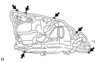
Text in Illustration *1 "TORX" Screw Install the 5 screws.
-
Using a T20H "TORX" driver, install the "TORX" screw.
-
-
INSTALL HEADLIGHT BRACKET LH
-
Install the headlight bracket LH with the 3 screws.
-
-
INSTALL FRONT BUMPER BAR REINFORCEMENT LH
-
Install the front bumper bar reinforcement LH with the 2 screws.
-
-
INSTALL NO. 1 HEADLIGHT BULB (w/ Driver Monitor Camera)
-
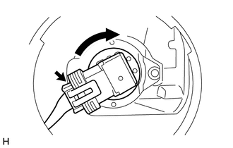
Turn the No. 1 headlight bulb in the direction indicated by the arrow and install it.
Note
Do not touch the glass part of the bulb.
-
Connect the connector.
-
-
INSTALL HEADLIGHT SOCKET COVER (w/ Driver Monitor Camera)
-
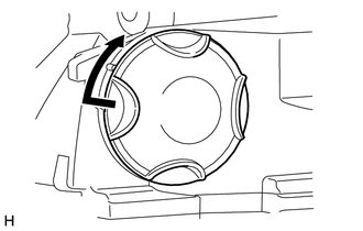
Turn the headlight socket cover in the direction indicated by the arrow and install it.
-
-
INSTALL HEADLIGHT GASKET
-
Install a new headlight gasket to the headlight light control ECU sub-assembly.
-
-
INSTALL HEADLIGHT LIGHT CONTROL ECU SUB-ASSEMBLY
-
Connect the connectors.
-
Install the headlight control ECU sub-assembly with the 4 screws.
-