LIGHTING SYSTEM Rear Vanity Light does not Illuminate
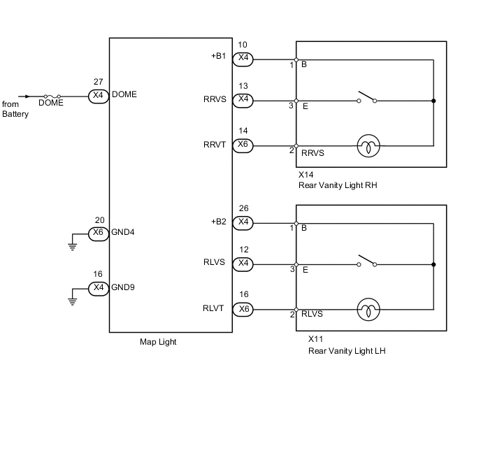
WIRING DIAGRAM
PROCEDURE
-
CHECK HARNESS AND CONNECTOR (MAP LIGHT - BATTER AND BODY GROUND)
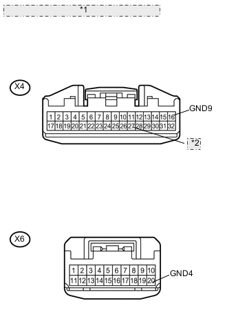
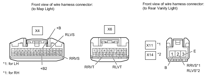
*1 Front view of wire harness connector: (to Map Light) *2 DOME
-
Disconnect the X4 and X6 light connectors.
-
Measure the resistance according to the value(s) in the table below.
Standard resistance Tester Connection Condition Specified Condition X6-20 (GND4) - Body ground Always Below 1 Ω X4-16 (GND9) - Body ground Always Below 1 Ω -
Measure the voltage according to the value(s) in the table below.
Standard voltage Tester Connection Condition Specified Condition X4-27 (DOME) - Body ground Always 11 to 14 V
NG 
REPAIR OR REPLACE HARNESS OR CONNECTOR
OK 
-
-
CHECK HARNESS AND CONNECTOR (MAP LIGHT - REAR VANITY LIGHT)
-
Disconnect the X4, X6, X11 (for LH) and X14 (for RH) light connectors.
-
Measure the resistance according to the value(s) in the table below.
Standard resistance for LH Tester Connection Condition Specified Condition X4-26 (+B2) - X11-1 (B) Always Below 1 Ω X4-12 (RLVS) - X11-3 (E) Always Below 1 Ω X6-16 (RLVT) - X11-2 (RLVS) Always Below 1 Ω X4-26 (+B2) - Body ground Always 10 kΩ or higher X4-12 (RLVS) - Body ground Always 10 kΩ or higher X6-16 (RLVT) - Body ground Always 10 kΩ or higher for RH Tester Connection Condition Specified Condition X4-10 (+B1) - X14-1 (B) Always Below 1 Ω X4-13 (RRVS) - X14-3 (E) Always Below 1 Ω X6-14 (RRVT) - X14-2 (RRVS) Always Below 1 Ω X4-10 (+B) - Body ground Always 10 kΩ or higher X4-13 (RRVS) - Body ground Always 10 kΩ or higher X6-14 (RRVT) - Body ground Always 10 kΩ or higher
NG
REPAIR OR REPLACE HARNESS OR CONNECTOR
OK
-
-
CHECK REAR VANITY LIGHT ASSEMBLY (OPERATION)
-
Check that the malfunction disappears when the rear vanity light is replaced with a normal one Click here.
OK Malfunction disappears
OK
REPLACE REAR VANITY LIGHT ASSEMBLY Click here
NG
REPLACE MAP LIGHT ASSEMBLY Click here
-