LIGHTING SYSTEM Inside Handle Light does not Illuminate
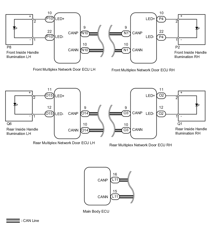
WIRING DIAGRAM
CAUTION / NOTICE / HINT
Note
First perform the communication function inspections in HOW TO PROCEED WITH TROUBLESHOOTING to confirm that there are no CAN communication malfunctions before troubleshooting this symptom.
PROCEDURE
-
CONFIRM LIGHT POSITION
-
Check the malfunctioning inside handle light.
Result Result Proceed to Front LH A Front RH B Rear LH C Rear RH D All E
B 
PERFORM ACTIVE TEST USING GTS (INSIDE HANDLE ILLUMINATION) Click here
C
PERFORM ACTIVE TEST USING GTS (INSIDE HANDLE ILLUMINATION) Click here
D
PERFORM ACTIVE TEST USING GTS (INSIDE HANDLE ILLUMINATION) Click here
E 
REPLACE MAIN BODY ECU
A 
-
-
PERFORM ACTIVE TEST USING GTS (INSIDE HANDLE ILLUMINATION)
-
Using the GTS, read the Data List.
Driver Door (for LHD) Tester Display Test Part Control Range Inside handle illumination Inside handle illumination operation OFF - ON Passenger Door (for RHD) Tester Display Test Part Control Range Inside handle illumination Inside handle illumination operation OFF - ON OK Inside handle illumination condition is switched by Active Test.
OK
REPLACE MAIN BODY ECU
NG
-
-
INSPECT FRONT INSIDE HANDLE ILLUMINATION LH
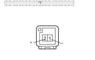
*1 Component without harness connected: (Front Inside Handle Illumination LH)
-
Remove the front inside handle light LH.
-
Apply battery voltage to the inside handle illumination and check the illumination condition.
OK Measurement Condition Specified Condition Battery positive (+) → Terminal 2 (+)
Battery negative (-) → Terminal 1 (-)
Inside handle light illumination on
NG
REPLACE FRONT INSIDE HANDLE ILLUMINATION LH Click here
OK
-
-
CHECK HARNESS AND CONNECTOR (FRONT DOOR ECU LH - FRONT INSIDE HANDLE ILLUMINATION LH)
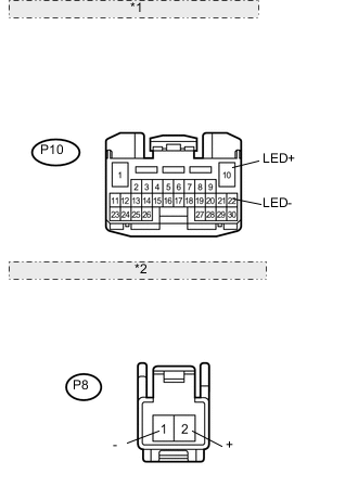
*1 Front view of wire harness connector: (to Front Door ECU LH) *2 Front view of wire harness connector: (to Front Inside Handle Illumination LH)
-
Disconnect the P10 ECU connector.
-
Disconnect the P8 light connector.
-
Measure the resistance according to the value(s) in the table below.
Standard resistance Tester Connection Condition Specified Condition P8-1 (-) - P10-22 (LED-) Always Below 1 Ω P8-2 (+) - P10-10 (LED+) Always Below 1 Ω P8-1 (-) - Body ground Always 10 kΩ or higher P8-2 (+) - Body ground Always 10 kΩ or higher
OK
REPLACE FRONT MULTIPLEX NETWORK DOOR ECU LH Click here
NG
REPAIR OR REPLACE HARNESS OR CONNECTOR
-
-
PERFORM ACTIVE TEST USING GTS (INSIDE HANDLE ILLUMINATION)
-
Using the GTS, perform the Active Test.
Passenger Door (for LHD) Tester Display Test Part Control Range Inside handle illumination Inside handle illumination operation OFF - ON Driver Door (for RHD) Tester Display Test Part Control Range Inside handle illumination Inside handle illumination operation OFF - ON OK Inside handle illumination condition is switched by Active Test.
OK
REPLACE MAIN BODY ECU
NG
-
-
INSPECT FRONT INSIDE HANDLE ILLUMINATION RH
*1 Component without harness connected: (Front Inside Handle Illumination RH)
-
Remove the front inside handle.
-
Apply battery voltage to the inside handle illumination and check the illumination condition.
OK Measurement Condition Specified Condition Battery positive (+) → Terminal 2 (+)
Battery negative (-) → Terminal 1 (-)
Inside handle light illumination on
NG
REPLACE FRONT INSIDE HANDLE ILLUMINATION RH Click here
OK
-
-
CHECK HARNESS AND CONNECTOR (FRONT DOOR ECU RH - FRONT INSIDE HANDLE ILLUMINATION RH)
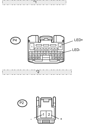
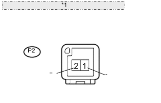
*1 Front view of wire harness connector: (to Front Door ECU RH) *2 Front view of wire harness connector: (to Front Inside Handle Illumination RH)
-
Disconnect the P4 ECU connector.
-
Disconnect the P2 light connector.
-
Measure the resistance according to the value(s) in the table below.
Standard resistance Tester Connection Condition Specified Condition P2-1 (-) - P4-22 (LED-) Always Below 1 Ω P2-2 (+) - P4-10 (LED+) Always Below 1 Ω P2-2 (+) - Body ground Always 10 kΩ or higher P2-1 (-) - Body ground Always 10 kΩ or higher
OK
REPLACE FRONT MULTIPLEX NETWORK DOOR ECU RH Click here
NG
REPAIR OR REPLACE HARNESS OR CONNECTOR
-
-
PERFORM ACTIVE TEST USING GTS (INSIDE HANDLE ILLUMINATION)
-
Using the GTS, perform the Active Test.
Rear Left Door Tester Display Test Part Control Range Inside handle illumination Inside handle illumination operation OFF - ON OK Inside handle illumination condition is switched by Active Test.
OK
REPLACE MAIN BODY ECU
NG
-
-
INSPECT REAR INSIDE HANDLE ILLUMINATION LH
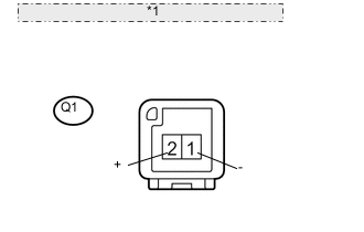
*1 Component without harness connected: (Rear Inside Handle Illumination LH)
-
Remove the rear inside handle light.
-
Apply battery voltage to the inside handle illumination and check the illumination condition.
OK Measurement Condition Specified Condition Battery positive (+) → Terminal 2 (+)
Battery negative (-) → Terminal 1 (-)
Inside handle light illumination on
NG
REPLACE REAR INSIDE HANDLE ILLUMINATION LH Click here
OK
-
-
CHECK HARNESS AND CONNECTOR (REAR DOOR ECU LH - REAR INSIDE HANDLE ILLUMINATION LH)
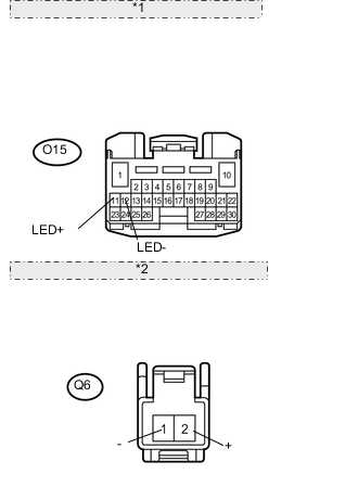
*1 Front view of wire harness connector: (to Rear Door ECU LH) *2 Front view of wire harness connector: (to Rear Inside Handle Illumination LH)
-
Disconnect the O15 ECU connector.
-
Disconnect the Q6 light connector.
-
Measure the resistance according to the value(s) in the table below.
Standard resistance Tester Connection Condition Specified Condition Q6-1 (-) - O15-12 (LED-) Always Below 1 Ω Q6-2 (+) - O15-11 (LED+) Always Below 1 Ω Q6-1 (-) - Body ground Always 10 kΩ or higher Q6-2 (+) - Body ground Always 10 kΩ or higher
OK
REPLACE REAR MULTIPLEX NETWORK DOOR ECU LH Click here
NG
REPAIR OR REPLACE HARNESS OR CONNECTOR
-
-
PERFORM ACTIVE TEST USING GTS (INSIDE HANDLE ILLUMINATION)
-
Using the GTS, perform the Active Test.
Rear Right Door Tester Display Test Part Control Range Inside handle illumination Inside handle illumination operation OFF - ON OK Inside handle illumination condition is switched by Active Test.
OK
REPLACE MAIN BODY ECU
NG
-
-
INSPECT REAR INSIDE HANDLE ILLUMINATION RH ASSEMBLY
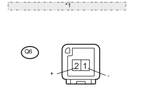
*1 Component without harness connected: (Rear Inside Handle Illumination RH)
-
Remove the rear inside handle light.
-
Apply battery voltage to the inside handle illumination and check the illumination condition.
OK Measurement Condition Specified Condition Battery positive (+) → Terminal 2 (+)
Battery negative (-) → Terminal 1 (-)
Inside handle light illumination on
NG
REPLACE REAR INSIDE HANDLE ILLUMINATION RH Click here
OK
-
-
CHECK HARNESS AND CONNECTOR (REAR DOOR ECU RH - REAR INSIDE HANDLE ILLUMINATION RH)
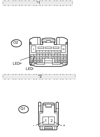
*1 Front view of wire harness connector: (to Rear Door ECU RH) *2 Front view of wire harness connector: (to Rear Inside Handle Illumination RH)
-
Disconnect the O2 ECU connector.
-
Disconnect the Q1 light connector.
-
Measure the resistance according to the value(s) in the table below.
Standard resistance Tester Connection Condition Specified Condition Q1-1 (-) - O2-12 (LED-) Always Below 1 Ω Q1-2 (+) - O2-11 (LED+) Always Below 1 Ω Q1-1 (-) - Body ground Always 10 kΩ or higher Q1-2 (+) - Body ground Always 10 kΩ or higher
OK
REPLACE REAR MULTIPLEX NETWORK DOOR ECU RH Click here
NG
REPAIR OR REPLACE HARNESS OR CONNECTOR
-