ENGINE IMMOBILISER SYSTEM TERMINALS OF ECU
-
CHECK ENGINE SWITCH

-
Disconnect the L36 switch connector.
-
Measure the resistance of the wire harness.
Terminal No. (Symbols) Wiring Color Terminal Description Condition Specified Condition L36-5 (GND) - Body ground W - Body ground Ground Always Below 1 Ω
-
If the result is not as specified, there may be a malfunction on the wire harness side.
-
-
Reconnect the L36 switch connector.
-
Measure the resistance and voltage of the connector.
Terminal No. (Symbols) Wiring Color Terminal Description Condition Specified Condition L36-8 (AGND) - Body ground L - Body ground Ground Always Below 1 Ω L36-14 (VC5) - L36-8 (AGND) V - L Power supply Key is not in cabin Below 1 V Press engine switch* 4.6 to 5.4 V L36-10 (CODE) - L36-8 (AGND) W - L Demodulated signal of key code data Key is not in cabin Below 1 V Press engine switch and hold key close to engine switch* Pulse generation (see waveform 1) L36-9 (TXCT) - L36-8 (AGND) BE - L Key code output signal Key is not in cabin Below 1 V Press engine switch and hold key close to engine switch* Pulse generation (see waveform 2) Tech Tips
*: Remove the key's battery before performing this inspection.
-
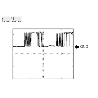
*1 Waveform 1: Using an oscilloscope, check the waveform 1.
Waveform 1 (Reference): Item Content Terminal No. (Symbols) L36-10 (CODE) - L36-8 (AGND) Tool Setting 2 V/DIV., 20 msec./DIV. Condition Press engine switch and hold key close to engine switch* Tech Tips
*: Remove the key's battery before performing this inspection.
-
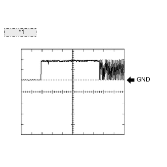
*1 Waveform 2: Using an oscilloscope, check the waveform 2.
Waveform 2 (Reference): Item Content Terminal No. (Symbols) L36-9 (TXCT) - L36-8 (AGND) Tool Setting 2 V/DIV., 20 msec./DIV. Condition Press engine switch and hold key close to engine switch* Tech Tips
*: Remove the key's battery before performing this inspection.
-
-
CHECK CERTIFICATION ECU
-
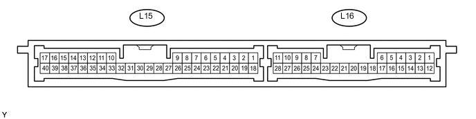
Disconnect the L15 ECU connector.
-
Measure the resistance and voltage of the wire harness side connector.
Terminal No. (Symbols) Wiring Color Terminal Description Condition Specified Condition L15-17 (E) - Body ground W-B - Body ground Ground Always Below 1 Ω L15-1 (+B1) - L15-17 (E) L - W-B +B power supply Always 11 to 14 V L15-18 (IG) - L15-17 (E) L - W-B Ignition power supply Engine switch off Below 1 V Engine switch on (IG) 11 to 14 V
-
If the result is not as specified, there may be a malfunction on the wire harness side.
-
-
Reconnect the L15 ECU connector.
-
Measure the resistance and voltage of the connector.
Terminal No. (Symbols) Wiring Color Terminal Description Condition Specified Condition L15-40 (AGND) - Body ground L - Body ground engine switch ground Always Below 1 Ω L15-30 (VC5) - L15-40 (AGND) V - L Engine switch power supply Key is not in cabin Below 1 V Press engine switch* 4.6 to 5.4 V L15-9 (CODE) - L15-40 (AGND) W - L Engine switch CODE input Key is not in cabin Below 1 V Press engine switch and hold key close to engine switch* Pulse generation (see waveform 1) L15-8 (TXCT) - L15-40 ()AGND BE - L Engine switch TX output Key is not in cabin Below 1 V Press engine switch and hold key close to engine switch* Pulse generation (see waveform 2) Tech Tips
*: Remove the key's battery before performing this inspection.
-
*1 Waveform 1: Using an oscilloscope, check the waveform 1.
Waveform 1 (Reference): Item Content Terminal No. (Symbols) L15-9 (CODE) - L15-40 (AGND) Tool Setting 2 V/DIV., 20 msec./DIV. Condition Press engine switch and hold key close to engine switch* Tech Tips
*: Remove the key's battery before performing this inspection.
-
*1 Waveform 2: Using an oscilloscope, check the waveform 2.
Waveform 2 (Reference): Item Content Terminal No. (Symbols) L15-8 (TXCT) - L15-40 (AGND) Tool Setting 2 V/DIV., 20 msec./DIV. Condition Press engine switch and hold key close to engine switch* Tech Tips
*: Remove the key's battery before performing this inspection.
-
-
CHECK ID CODE BOX

-
Disconnect the L32 ECU connector.
-
Measure the resistance and voltage of the wire harness side connector.
Terminal No. (Symbols) Wiring Color Terminal Description Condition Specified Condition L32-8 (GND) - Body ground W-B - Body ground Ground Always Below 1 Ω L32-1 (+B) - L32-8 (GND) L - W-B +B power supply Always 11 to 14 V
-
If the result is not as specified, there may be a malfunction on the wire harness side.
-
-
Reconnect the L32 ECU connector.
-
Measure the voltage of the connector.
Terminal No. (Symbols) Wiring Color Terminal Description Condition Specified Condition L32-5 (EFII) - L32-8 (GND) B - W-B*1
Y - W-B*2
ECM input signal*1
Telephone transceiver input signal*2
Engine switch off Below 1 V Within 3 seconds after starter operates and initial combustion occurs, or within 3 seconds after engine switch first turned on (IG) after battery disconnected and connected Pulse generation (see waveform 1) L32-6 (EFIO) - L32-8 (GND) L - W-B*1
GR - W-B*2
ECM output signal*1
Telephone transceiver output signal*2
Engine switch off Below 1 V Within 3 seconds after starter operates and initial combustion occurs, or within 3 seconds after engine switch first turned on (IG) after battery disconnected and connected Pulse generation (see waveform 2) Tech Tips
*1: w/o Blocking System
*2: w/ Blocking System
-

*1 Waveform 1: Using an oscilloscope, check the waveform 1.
Waveform 1 (Reference): Item Content Terminal No. (Symbols) L32-5 (EFII) - L32-8 (GND) Tool Setting 10 V/DIV., 100 msec./DIV. Condition Within 3 seconds after starter operates and initial combustion occurs, or within 3 seconds after engine switch first turned on (IG) after battery disconnected and connected -

*1 Waveform 2: Using an oscilloscope, check the waveform 2.
Waveform 2 (Reference): Item Content Terminal No. (Symbols) L32-6 (EFIO) - L32-8 (GND) Tool Setting 10 V/DIV., 100 msec./DIV. Condition Within 3 seconds after starter operates and initial combustion occurs, or within 3 seconds after engine switch first turned on (IG) after battery disconnected and connected
-
-
CHECK MAIN BODY ECU (DRIVER SIDE JUNCTION BLOCK)
-
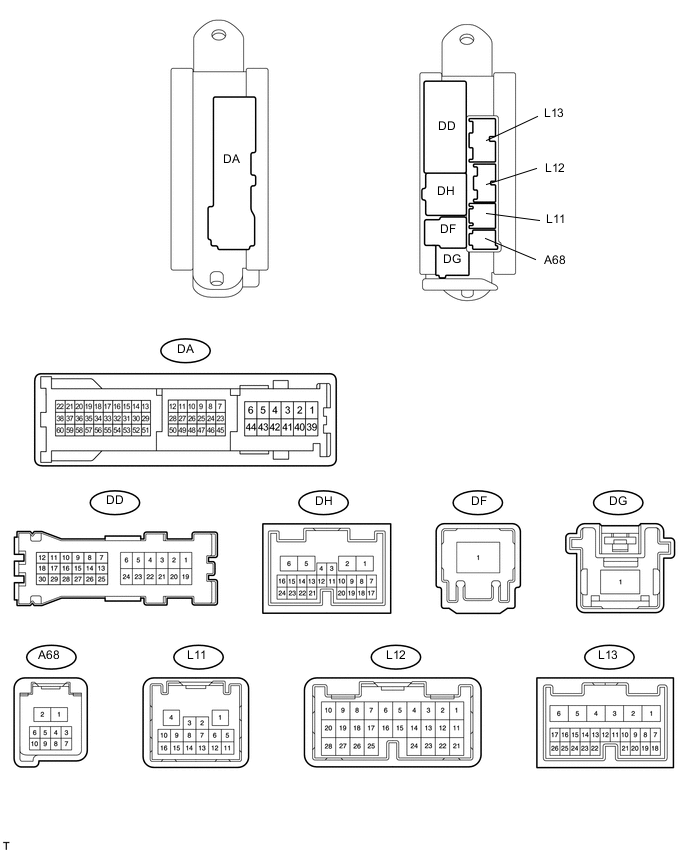
Disconnect the DA and DF ECU connectors.
-
Measure the resistance and voltage according to the value(s) in the table below.
Terminal No. (Symbols) Wiring Color Terminal Description Condition Specified Condition DA-40 (GND2) - Body ground W-B - Body ground Ground Always Below 1 Ω DA-41 (GND2) - Body ground W-B - Body ground Ground Always Below 1 Ω DF-1 (ACC) - GND2 (DA-40) B - W-B ACC power supply Engine switch off Below 1 V Engine switch on (ACC) 11 to 14 V DF-1 (IG) - DA-40 (GND2) B - W-B IG power supply Engine switch off Below 1 V Engine switch on (IG) 11 to 14 V
-
If the result is not as specified, there may be a malfunction on the wire harness side.
-
-
-
CHECK STEERING LOCK ACTUATOR (STEERING LOCK ECU)

-
Disconnect the L33 ECU connector.
-
Measure the resistance and voltage according to the value(s) in the table below.
Terminal No. (Symbols) Wiring Color Terminal Description Condition Specified Condition L33-2 (SGND) - Body ground BR - Body ground Ground Always Below 1 Ω L33-1 (GND) - Body ground W-B - Body ground Ground Always Below 1 Ω L33-7 (B) - Body ground P - Body ground +B power supply Always 11 to 14 V L33-6 (IG2) - Body ground L - Body ground Ignition power supply Engine switch off Below 1 V Engine switch on (IG) 11 to 14 V
-
If the result is not as specified, there may be a malfunction on the wire harness side.
-
-
-
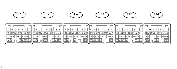
CHECK ECM (for 1UR-FSE)
-
Measure the resistance and voltage according to the value(s) in the table below.
Terminal No. (Symbols) Wiring Color Terminal Description Condition Specified Condition E3-1 (E1) - Body ground W-B - Body ground Ground Always Below 1 Ω E2-2 (E01) - Body ground W-B - Body ground Ground Always Below 1 Ω E2-1 (E02) - Body ground W-B - Body ground Ground Always Below 1 Ω A13-5 (E03) - Body ground W-B - Body ground Ground Always Below 1 Ω E3-4 (E04) - Body ground W-B - Body ground Ground Always Below 1 Ω A14-1 (EC) - Body ground W-B - Body ground Ground Always Below 1 Ω E2-5 (ME01) - Body ground W-B - Body ground Ground Always Below 1 Ω A14-7 (BATT) - E3-1 (E1) B - W-B Battery (for measuring battery voltage and for ECM memory) Always 9 to 14 V A13-2 (+B) - E3-1 (E1) B-W*1 - W-B
B*2 - W-B
Power source of ECM Engine switch off Below 1 V Engine switch on (IG) 9 to 14 V A13-1 (+B2) - E3-7 (E1) B-W*1 - W-B
B*2 - W-B
Power source of ECM Engine switch off Below 1 V Engine switch on (IG) 9 to 14 V A13-31 (IMI) - E3-1 (E1) L - W-B ID code box input signal Engine switch off Below 1 V Within 3 seconds after starter operates and initial combustion occurs, or within 3 seconds after engine switch first turned on (IG) after battery disconnected and connected Pulse generation (see waveform 1) A13-30 (IMO) - E3-1 (E1) B - W-B ID code box output signal Engine switch off Below 1 V Within 3 seconds after starter operates and initial combustion occurs, or within 3 seconds after engine switch first turned on (IG) after battery disconnected and connected Pulse generation (see waveform 2) Tech Tips
*1: for LHD
*2: for RHD
-
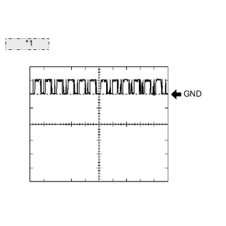
*1 Waveform 1: Using an oscilloscope, check the waveform 1.
Waveform 1 (Reference): Item Content Terminal No. (Symbols) A13-31 (IMI) - E3-1 (E1) Tool Setting 10 V/DIV., 100 msec./DIV. Condition Within 3 seconds after starter operates and initial combustion occurs, or within 3 seconds after engine switch first turned on (IG) after battery disconnected and connected -
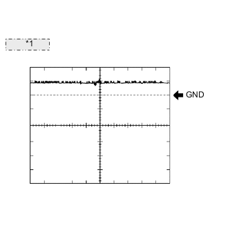
*1 Waveform 2: Using an oscilloscope, check the waveform 2.
Waveform 2 (Reference): Item Content Terminal No. (Symbols) A13-30 (IMO) - E3-1 (E1) Tool Setting 10 V/DIV., 100 msec./DIV. Condition Within 3 seconds after starter operates and initial combustion occurs, or within 3 seconds after engine switch first turned on (IG) after battery disconnected and connected
-
-
CHECK ECM (for 1UR-FE)
-
Measure the resistance and voltage according to the value(s) in the table below.
Terminal No. (Symbols) Wiring Color Terminal Description Condition Specified Condition E3-1 (E1) - Body ground W-B - Body ground Ground Always Below 1 Ω E2-2 (E01) - Body ground W-B - Body ground Ground Always Below 1 Ω E2-1 (E02) - Body ground W-B - Body ground Ground Always Below 1 Ω A13-5 (E03) - Body ground W-B - Body ground Ground Always Below 1 Ω E3-4 (E04) - Body ground W-B - Body ground Ground Always Below 1 Ω A14-1 (EC) - Body ground W-B - Body ground Ground Always Below 1 Ω E2-5 (ME01) - Body ground W-B - Body ground Ground Always Below 1 Ω A14-7 (BATT) - E3-1 (E1) B - W-B Battery (for measuring battery voltage and for ECM memory) Always 9 to 14 V A13-2 (+B) - E3-1 (E1) B - W-B Power source of ECM Engine switch off Below 1 V Engine switch on (IG) 9 to 14 V A13-1 (+B2) - E3-7 (E1) B - W-B Power source of ECM Engine switch off Below 1 V Engine switch on (IG) 9 to 14 V A13-31 (IMI) - E3-1 (E1) L - W-B ID code box input signal*1
Telephone transceiver input signal*2
Engine switch off Below 1 V Within 3 seconds after starter operates and initial combustion occurs, or within 3 seconds after engine switch first turned on (IG) after battery disconnected and connected Pulse generation (see waveform 1) A13-30 (IMO) - E3-1 (E1) B - W-B ID code box output signal*1
Telephone transceiver output signal*2
Engine switch off Below 1 V Within 3 seconds after starter operates and initial combustion occurs, or within 3 seconds after engine switch first turned on (IG) after battery disconnected and connected Pulse generation (see waveform 2) Tech Tips
*1: w/o Blocking System
*2: w/ Blocking System
-
*1 Waveform 1: Using an oscilloscope, check the waveform 1.
Waveform 1 (Reference): Item Content Terminal No. (Symbols) A13-31 (IMI) - E3-1 (E1) Tool Setting 10 V/DIV., 100 msec./DIV. Condition Within 3 seconds after starter operates and initial combustion occurs, or within 3 seconds after engine switch first turned on (IG) after battery disconnected and connected -
*1 Waveform 2: Using an oscilloscope, check the waveform 2.
Waveform 2 (Reference): Item Content Terminal No. (Symbols) A13-30 (IMO) - E3-1 (E1) Tool Setting 10 V/DIV., 100 msec./DIV. Condition Within 3 seconds after starter operates and initial combustion occurs, or within 3 seconds after engine switch first turned on (IG) after battery disconnected and connected
-
-
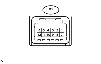
CHECK TELEPHONE TRANSCEIVER ASSEMBLY (w/ Blocking System)
-
Disconnect the L180 telephone transceiver assembly connector.
-
Measure the resistance and voltage according to the value(s) in the table below.
Terminal No. (Symbol) Wiring Color Terminal Description Condition Specified Condition L180-6 (IG2) - L180-9 (E) R - W-B Ignition power supply Engine switch on (IG) 9 to 16 V Engine switch off Below 1 V L180-12 (+B) - L180-9 (E) W - W-B +B power supply Always 9 to 16 V L180-9 (E) - Body ground W-B - Body ground Ground Always Below 1 Ω
-
If the result is not as specified, there may be a malfunction on the wire harness side.
-
-
Reconnect the L180 telephone transceiver assembly connector.
-
Measure the voltage according to the value(s) in the table below.
Terminal No. (Symbol) Wiring Color Terminal Description Condition Specified Condition L180-1 (BLK1) - L180-9 (E) Y - W-B ID code box (immobiliser code ECU) communication input Engine switch off 11 to 14 V L180-1 (BLK1) - L180-9 (E) Y - W-B ID code box (immobiliser code ECU) communication input Within 3 seconds of engine start or within 3 seconds of engine switch turned on (IG) after battery cable disconnected and reconnected Pulse generation
(See waveform 1)
L180-2 (BLK4) - L180-9 (E) GR - W-B ID code box (immobiliser code ECU) communication output Engine switch off Below 1 V L180-2 (BLK4) - L180-9 (E) GR - W-B ID code box (immobiliser code ECU) communication output Within 3 seconds of engine start or within 3 seconds of engine switch turned on (IG) after battery cable disconnected and reconnected Pulse generation
(See waveform 2)
L180-7 (BLK2) - L180-9 (E) B - W-B ECM communication output Engine switch off Below 1 V L180-7 (BLK2) - L180-9 (E) B - W-B ECM communication output Within 3 seconds of engine start or within 3 seconds of engine switch turned on (IG) after battery cable disconnected and reconnected Pulse generation
(See waveform 1)
L180-8 (BLK3) - L180-9 (E) G - W-B ECM communication input Engine switch off Below 1 V L180-8 (BLK3) - L180-9 (E) G - W-B ECM communication input Within 3 seconds of engine start or within 3 seconds of engine switch turned on (IG) after battery cable disconnected and reconnected Pulse generation
(See waveform 2)
-
*1 Waveform 1: Using an oscilloscope, check the waveform 1.
Waveform 1 (Reference): Item Content Terminal No. (Symbols)
-
L180-1 (BLK1) - L180-9 (E)
-
L180-7 (BLK2) - L180-9 (E)
Tool Setting 10 V/DIV., 100 msec./DIV. Condition Within 3 seconds of engine start or within 3 seconds of engine switch turned on (IG) after battery cable disconnected and reconnected -
-
*1 Waveform 2: Using an oscilloscope, check the waveform 2.
Waveform 2 (Reference): Item Content Terminal No. (Symbols)
-
L180-8 (BLK3) - L180-9 (E)
-
L180-2 (BLK4) - L180-9 (E)
Tool Setting 10 V/DIV., 100 msec./DIV. Condition Within 3 seconds of engine start or within 3 seconds of engine switch turned on (IG) after battery cable disconnected and reconnected -
-